|
|
You are here: GSI Wiki>CRY_EXP Web>MachineSignals (2026-02-26, MichaelLestinsky)
Machine Signals
The following shall give an overview of the electronic interfaces at the machine to specific signals, e.g. for data acquisition. All signals are arriving at the electronics hutch, TH2.033 at the top of the 19-in Rack EX2.Timing system

 Two interconnected NACON1 modules provide electronic signals for WhiteRabbit events. The events can be programmed through ParamModi.
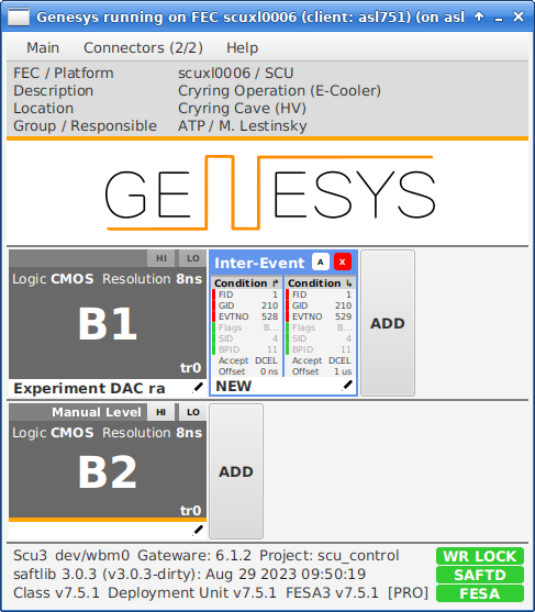
Generally, the low-level timing settings in Genesys
Two interconnected NACON1 modules provide electronic signals for WhiteRabbit events. The events can be programmed through ParamModi.
Generally, the low-level timing settings in Genesys- Injection Pulse
- Target on/off (gasjet, electron target, ... depends on experiment)
- Experiment DAQ on/off (flag for your DAQ when the Machine is in a process with measurement conditions)
- Experiment Drive in/out (Moving e.g. particle detectors, scrapers, ... in/out)
- Electron cooler beam is on/off
- Extraction Pulse
- TBA
- TBA
Beam diagnostics
 Two interconnected NIM modules type NACON1 provide access to all beam diagnostics singals from the machine, where they are available as ECL, NIM, or TTL pulse types.
- horizontal IonizationProfileMonitor MCP count rate (IPM)
- vertical IPM count rate
- ParametricCurrentTransformer
- IntegratingCurrentTransformer integral
- BeamPositionMonitor integral
- SchottkySpan0
- CryRadio
- RingRF
Experiment Signals
ElectronCooler
- Current: EcoolCurrentMeasurement
- Energy: ArnoldHV voltage divider, G35VoltageDivider, FC20VoltageDivider
Machine settings


| I | Attachment | Action | Size | Date | Who | Comment |
|---|---|---|---|---|---|---|
| |
IMG_6376.jpg | manage | 561 K | 2025-06-24 - 12:40 | MichaelLestinsky | Beam diagnostics signals |
| |
IMG_6377.jpg | manage | 587 K | 2025-06-24 - 12:45 | MichaelLestinsky | WR signals NACON1 |
| |
Screenshot_2024-03-06_11-47-19.png | manage | 76 K | 2024-03-06 - 11:48 | MichaelLestinsky | scuxl0006 Genesys screenshot |
| |
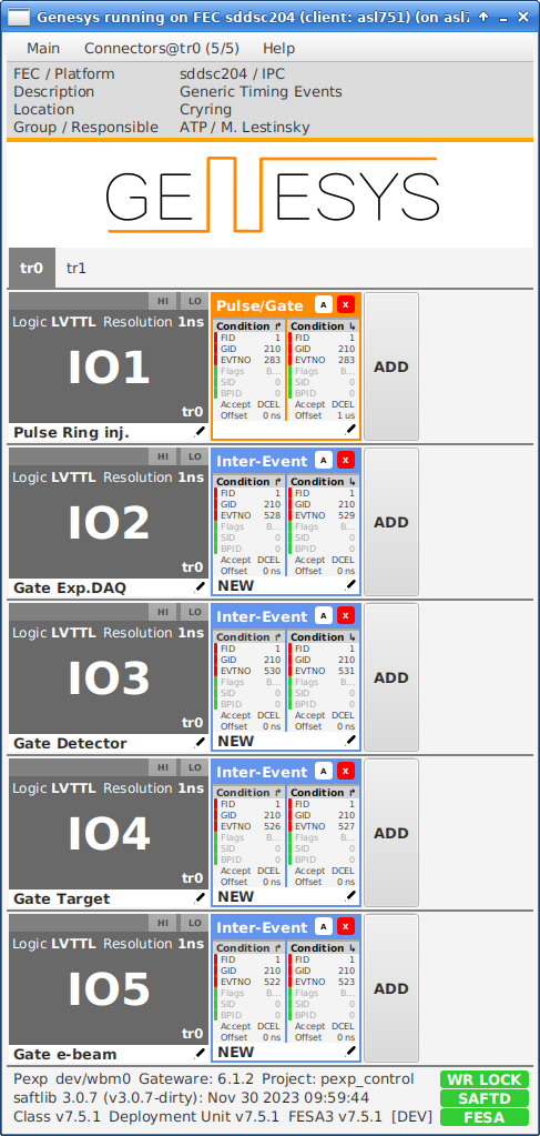
Screenshot_2024-03-06_12-52-01.png | manage | 142 K | 2024-03-06 - 12:52 | MichaelLestinsky | sddsc204 Genesys screenshot |
| |
Screenshot_2025-06-13_14-50-29.png | manage | 222 K | 2025-06-13 - 14:54 | MichaelLestinsky | ParamModi::Target Exp tab |
Please login to edit this topic
Topic revision: r33 - 2026-02-26, MichaelLestinsky
Ideas, requests, problems regarding GSI Wiki? Send feedback | Legal notice | Privacy Policy (german)