|
|
You are here: GSI Wiki>Epics Web>EpicsProjectsAndActivities>HardwarePlatforms>HadCon2>HadCon2MultipurposeControlsApi (2020-11-09, PeterZumbruch)
Multi-purpose control API implementation on HadCon2
Table of Content
| (short) | |
Introduction


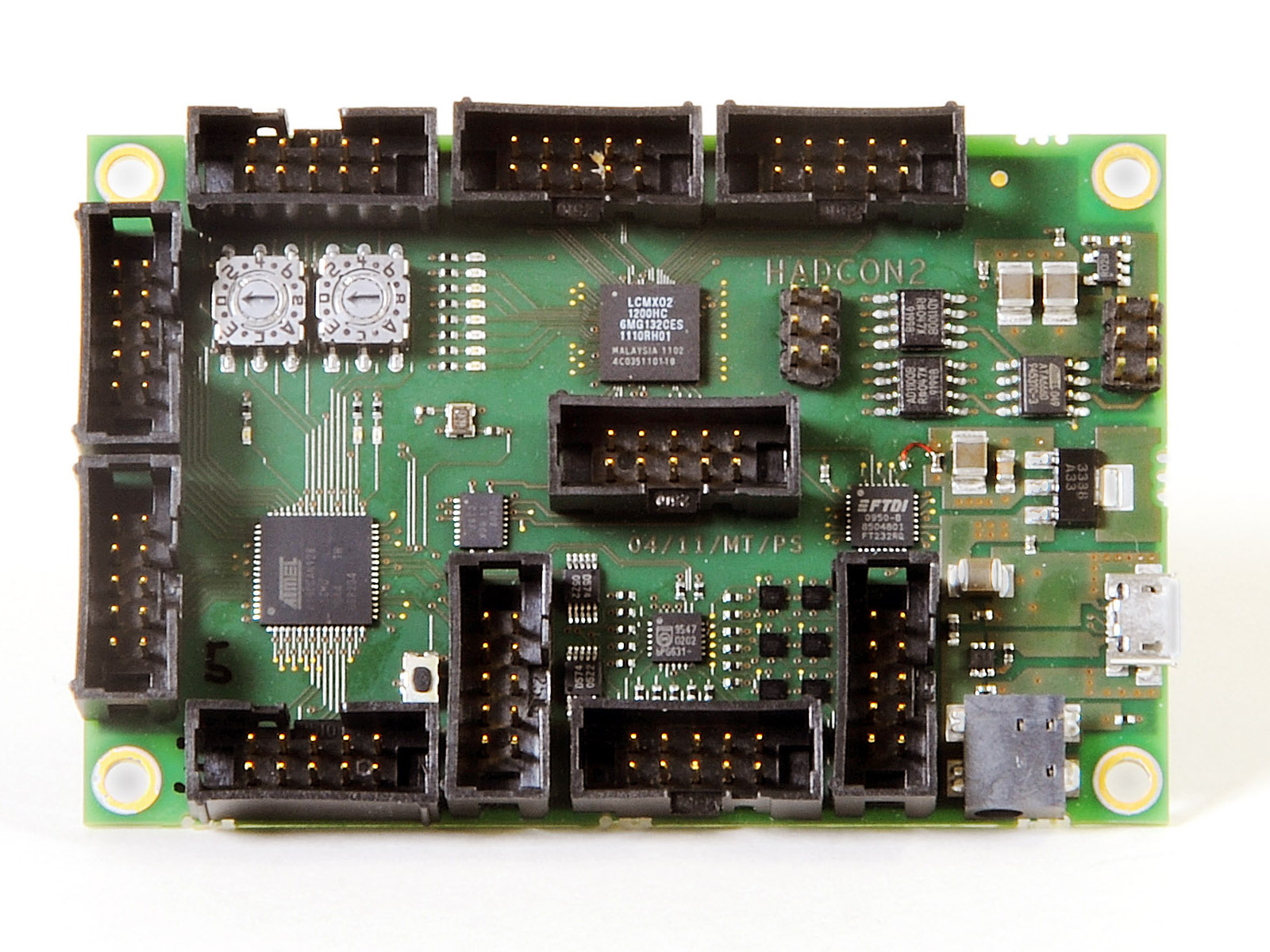
HadCon2 is a credit-card sized general purpose I/O module for detector and experiment controls as well as for small data acquisition systems.
 It is the successor of the discontinued first version HadCon ( HADControl/HadShoPoMo general purpose board, HadCon @ Epics Wiki).
The module has an ATMEL AT90CAN128 microcontroller providing a multitude of connectivity:
It is the successor of the discontinued first version HadCon ( HADControl/HadShoPoMo general purpose board, HadCon @ Epics Wiki).
The module has an ATMEL AT90CAN128 microcontroller providing a multitude of connectivity:
It doesn't have any CPU on board, but a USB connector to directly allow communication with any type and size of computer (e.g. PC, raspberry PI, dreamplug, ...) having an USB port on one side and at the other end the microcontroller and the FGPA. This communication is based on an ASCII-based protocol in view of easy implementation in detector control systems like e.g. EPICS and LabVIEW.
It is the successor of the discontinued first version HadCon ( HADControl/HadShoPoMo general purpose board, HadCon @ Epics Wiki).
The module has an ATMEL AT90CAN128 microcontroller providing a multitude of connectivity:
I2C (8/4 fold (intern/extern) multiplexer), 6 channel 1-wire master, 8-channel 8bit DAC, galvanically isolated CAN - high-speed transceiver, 8-channel 10-bit SAR ADC, byte-oriented SPI, in total up-to 53 programmable I/O lines and optionally a Lattice MachX02 FPGA for fast data processing tasks.
While the discontinued precursor HadCon had an SoC on-board, its successor HadCon2 has broken up this concept in favour of a more open access:It doesn't have any CPU on board, but a USB connector to directly allow communication with any type and size of computer (e.g. PC, raspberry PI, dreamplug, ...) having an USB port on one side and at the other end the microcontroller and the FGPA. This communication is based on an ASCII-based protocol in view of easy implementation in detector control systems like e.g. EPICS and LabVIEW.
- Summarizing:
- Microcontroller: ATMEL AT90CAN128
- I2C
- CANbus
- SPI
- ADCs
- ...
- FPGA: Lattice MachX02-1200-HC
- FTDI USB to serial UART interface
- USB 2.0 connector
- Power over USB
- I2C devices
- 6 × Single-Channel 1-Wire Master
- 1 × 8-channel I2C-bus multiplexer with reset
- 2 × 4-channel 8-Bit DAC - Digital-to-Analog Converter
- galvanically isolated CAN - High-speed CAN Transceiver
- optional external power supply
- 2 × Rotary Code Switches, hexadecimal coding
- Reset Button for ATMEL
- 11 × LED's, free programmable
- Microcontroller: ATMEL AT90CAN128
-- PeterZumbruch - 2014-02-07
Objective
This project's objective is to adopt the project specification made for the API for multi-purpose control implementation on HadCon to the new but very similar hardware of HadCon2. This includes the access to the different devices via an ASCII based protocol. This provides:- ATMEL's internal
- ADC, SPI, CANbus, I2C, Registers
- Communication with MachX02
- I2C
- 1-Wire bus implementation via I2C
to access 1-wire sensors and actuators:- ADCs
- Temperature sensors
- Switches
- DACs
- 1-Wire bus implementation via I2C
- Relay applications
- ...
Setup
Hardware
- HadCon2
- Power supply, via USB
- Devices to connect to
- CAN
- I2C
- 1-Wire via I2C
- DAC via I2C
- Registers
- ...
- ! Only needed for programming
- AVR-USB-JTAG Connector (olimex)
- make sure the user accessing the AVR-USB-JTAG has sufficient permissions
- suse-linux:
- user should be member of group
dialout - before accessing change group by issuing the command:
newgrp dialout- TODO: Check: are there smarter alternatives ???
- user should be member of group
- suse-linux:
- q.v. "usbdev - dynamic dev symbolic link and proper access rights", mentioned below
- make sure the user accessing the AVR-USB-JTAG has sufficient permissions
- AVR-USB-JTAG Connector (olimex)
Documentation
Software
- repository: https://git.gsi.de/HadCon2/Firmware/HadCon2
- !HadCon2 : Microcontroller Code
- Branches: (q.v. Git Workflow)
- 4.x.y: version
- master: (link to subversion)
- dev: branch to consolidate before committing/merging into master
- Branches: (q.v. Git Workflow)
- !HadCon2 : Microcontroller Code
- Access
- read: https
- further access on request, ask P.Zumbruch
- needs login access to git.gsi.de to become a member
Code Repositories
git
git.gsi.de
-
The code is available on the gitlab repository of GSI
Tar Balls & ELFs
- Programming:
- using
avrdudeyou can program: (asuming HadCon2 jtag chain)$> avrdude -v -P /dev/ttyUSBx -pc128 -c jtagmkI -x jtagchain=0,1,0,8 -Uflash:w:<hadcon>.elf- Don't forget setting fuses, to be done when HadCon2 is programmed the first time:
$> avrdude -v -P /dev/ttyUSBx -pc128 -c jtagmkI -x jtagchain=0,1,0,8 -Uefuse:w:0xff:m -Uhfuse:w:0x19:m -Ulfuse:w:0xe0:m
- Don't forget setting fuses, to be done when HadCon2 is programmed the first time:
- HadCon Note
- In case of HadCon(1) use
jtagchain=0,1,0,4instead
- using obsolete
avariceyou can program: (asuming HadCon2 jtag chain)avarice -c 0,1,0,8 --jtag /dev/ttyUSBx -B 1000000 --erase --program --file <hadcon>.elf- Don't forget setting fuses, to be done when HadCon2 is programmed the first time:
avarice -c 0,1,0,8 --jtag /dev/ttyUSBx -B 1000000 -W ff19e0
- Don't forget setting fuses, to be done when HadCon2 is programmed the first time:
- HadCon Note
- In case of HadCon(1) use
jtagchain=0,1,0,4instead
- using
Tar ball, including ELFs
| x.0 | x.1 | x.2 | x.3 | x.4 | x.5 | x.6 | |
|---|---|---|---|---|---|---|---|
| 1.x | 1.0 | ||||||
| 2.x | 2.0 | 2.1 | |||||
| 3.x | 3.0 | 3.1 | |||||
| 4.x | 4.0 | 4.1 | 4.2 | 4.3 | 4.4 | 4.5 | |
| 4.3.1 | 4.4.1 | 4.5.1 | 4.6.1 | ||||
| 4.3.2 | 4.4.2 | 4.6.2 | |||||
| 4.6.2.1 | |||||||
| 4.3.2 | |||||||
| 4.3.3 | |||||||
| 4.6.3-Apfel | |||||||
| 4.6.3_MM |
HadCon2 - ELF 32-bit LSB executable, Atmel AVR 8-bit, version 1 (SYSV), statically linked, not stripped
| x.0 | x.1 | x.2 | x.3 | x.4 | x.5 | x.6 | |
|---|---|---|---|---|---|---|---|
| 1.x | |||||||
| 2.x | |||||||
| 3.x | |||||||
| 4.x | 4.3.2 - hadcon1 | ||||||
| 4.3.2 - hadcon2 | |||||||
| 4.3.3 - hadcon1 | |||||||
| 4.3.3 - hadcon2 | |||||||
| 4.4.1 - hadcon1 | |||||||
| 4.4.1 - hadcon2 | |||||||
| 4.6.2 | |||||||
| 4.6.2.1 | |||||||
| 4.6.3-Apfel | |||||||
| 4.6.3_MM |
-- PeterZumbruch - 2020-12-11
ATMEL
- programming with olimex:
/dev/olimex - access:
/dev/hadcon2An automatic assignment of specified USB devices to thosedevports is described here
at "usbdev - dynamic dev symbolic link and proper access rights" - AVR - gcc based
- avr : e.g.
zypper se avr - Warning: reading http://www.nongnu.org/avr-libc/bugs.html pointing to http://gcc.gnu.org/bugzilla/show_bug.cgi?id=30289 tells us, that
memsetis wrong compiled- avr-gcc 3.3.5 - OK
- fixed in 4.1.3, 4.2 branch, and >= 4.3.0.
- typically you get 4.1.2

- avr : e.g.
- avr-gcc, avr-libc
- openSuse - Repository: (from: http://www.mikrocontroller.net/articles/AVR_Eclipse#openSuSE)
-
zypper ar http://download.opensuse.org/repositories/CrossToolchain:/avr/openSUSE_13.1/ <Some Name> -
zypper install avr-libc cross-avr-gcc
-
- openSuse - Repository: (from: http://www.mikrocontroller.net/articles/AVR_Eclipse#openSuSE)
- AVRDUDE - AVR Downloader/UploaDEr
- AVRDUDE is a utility to download/upload/manipulate the ROM and EEPROM contents of AVR microcontrollers using the in-system programming technique (ISP).
- https://www.nongnu.org/avrdude/
- Programming:
$> avrdude -v -P /dev/ttyUSBx -pc128 -c jtagmkI -x jtagchain=0,1,0,8 -Uflash:w:<hadcon>.elf- Don't forget setting fuses, to be done when HadCon2 is programmed the first time:
$> avrdude -v -P /dev/ttyUSBx -pc128 -c jtagmkI -x jtagchain=0,1,0,8 -Uefuse:w:0xff:m -Uhfuse:w:0x19:m -Ulfuse:w:0xe0:m
- HadCon Note
- In case of HadCon(1) use
jtagchain=0,1,0,4instead
- Don't forget setting fuses, to be done when HadCon2 is programmed the first time:
- obsolete alternative to avrdude
- Development of avarice has been discontiuned
- avarice: http://avarice.sourceforge.net
- Programming:
avarice -c 0,1,0,8 --jtag /dev/ttyUSBx -B 1000000 --erase --program --file <hadcon>.elf- Don't forget setting fuses, to be done when HadCon2 is programmed the first time:
avarice -c 0,1,0,8 --jtag /dev/ttyUSBx -B 1000000 -W ff19e0
- HadCon Note
- In case of HadCon(1) use
jtagchain=0,1,0,4instead
- Don't forget setting fuses, to be done when HadCon2 is programmed the first time:
- Note:
- avarice does not support the --program feature from version 2.12 on, so make sure you have maximal 2.11.
- Local build:
- Download sources :
- %FOREACH{"av_version" in="2.11,2.12"}%
- avarice-$av_version (local copy) %NEXT{"av_version"}%
- Patches
- Download patches for g++ -version ≥ 6.4:
- %FOREACH{"av_version" in="2.11,2.12"}%
- $av_version
- %FOREACH{"av_file" in="pragma.h,jtagrw.cc"}%
- patch.avarice-$av_version.$av_file %NEXT{"av_file"}%
- $av_version
- Apply Patches:
- %FOREACH{"av_version" in="2.11,2.12"}%
- $av_version
- %FOREACH{"av_file" in="pragma.h,jtagrw.cc"}%
patch src/$av_file < patch.$av_version.$av_file %NEXT{"av_file"}%
- $av_version
- Download patches for g++ -version ≥ 6.4:
- build
-
-
./configure && makeor -
./configure && make && make install
-
-
- Download sources :
- Pitfalls & Obstacles:
-
- programming
- HadCon's and HadCon2's CPLD/FPGA size differs
avaricemust have the right arguments
$>avarice -c 0,1,0,8 --jtag /dev/olimex -B 1000000 --erase --program --file api.elf - Set fuses
- First time you are programming a new hadcon board with Olimex (s.below) you have to set fuses (up-to-now I don't now what this means) by issuing from your cross compiling computer the following sequence:
$> avarice -c 0,1,0,8 --jtag /dev/olimex -B 1000000 -W ff19e0
-
- AVR Knowledge:
- AVR Tutorial (german): http://www.mikrocontroller.net/articles/AVR-GCC-Tutorial
- Helper to show memory consumption add it to
PATH - AVR http://www.rn-wissen.de/index.php/Avr-gcc (german)
- Tipps and Tricks: http://www.rn-wissen.de/index.php/Avr-gcc#Optimierungen.2C_Tipps_.26_Tricks (german)
- AVR libc manual: http://www.nongnu.org/avr-libc/user-manual/index.html
Toolchain & Access
Prerequisites
Since USB devices are not assigned statically and may change, in the following it is assumed that the serial/usb devices used to program/access the Hadcon are:AVR
avrdude
avarice
Docs / Tutorials / Help
Supported devices
1-wire
Tweaks
- Program space:
- Memory usage:
Program Space (Harvard Architecture)
Memory usage
-- PeterZumbruch - 2020-08-04
-- PeterZumbruch - 2020-12-10
Operation
Basic Operation Principles
The basic operation principle is that- Any device communicates via the USB interface with the μController sending and receiving keyword based ASCII streams/strings (see Protocol for details)
- input string is terminated by <LF> or <CR>
- μController provides the communication with the (external) devices
- In general a command and its possible response e.g.
HELPis sent/retrieved from the master to the ATMEL with e.g. by listening to/dev/ttyUSBxwhile sending the command to the same device, i.e. in the easiest case (including an endless while loop for an automatic reconnect)replace$> while :; do sleep 1; cat /dev/ttyUSBx; done &
$> echo "HELP" >/dev/ttyUSBxxby the corresponding integer - To access the device the user has to have the right permissions, e.g.
dialout, uselsandgroupsto find out current settings$> ls -l /dev/ttyUSB*
crw-rw-rwT 1 root users 188, 0 Jan 21 10:38 /dev/ttyUSB0
crw-rw---T 1 root dialout 188, 1 Jan 21 10:38 /dev/ttyUSB1
$> groups epics
epics : epics dialout epicsadm - It might be necessary that the properties of the serial devices has to be changed. Currently these
sttyare working$> stty -F /dev/ttyUSBx -opost -onlcr -isig -icanon -iexten -echo -echoe -echok -echoctl -echoke 115200- Output settings:
- -opost
- do not post-process output
- -onlcr
- do not translate newline to carriage return-newline
- Local settings:
- -isig
- do not enable interrupt, quit, and suspend special characters
- -icanon
- do not enable erase, kill, werase, and rprnt special characters
- -iexten
- do not enable non-POSIX special characters
- -echo
- do not echo input characters
- -echoe
- do not echo erase characters as backspace-space-backspace
- -echok
- do not echo a newline after a kill character
- -echoctl
- do not echo control characters in hat notation ('^c')
- -echoke
- kill all line by obeying the
echoctlandechoksetting - 115200
- sets the speed to 115200 Bit/s
Communication Tools
Linux
cat / echo
replace$> stty -F /dev/ttyUSBx -opost -onlcr -isig -icanon -iexten -echo -echoe -echok -echoctl -echoke 115200
$> while :; do sleep 1; cat /dev/ttyUSBx; done &
$> echo "HELP" >/dev/ttyUSBxxby the corresponding integerhadcon
IRC-like environment with command history (over several sessions) and command line editing all included- requires
tmuxinstalled - copy the following three commands to your
~/bin- hadcon
- hadcon_command_only.pl (remove the .txt at end of filename)
- slurp_serial
replace$> stty -F /dev/ttyUSBx -opost -onlcr -isig -icanon -iexten -echo -echoe -echok -echoctl -echoke 115200
$> hadcon /dev/ttyUSBxxby the corresponding integerpicocom
replacepicocom --b 115200 -l /dev/ttyUSBx -d 8 -p n -f n --echo --omap crlf --imap lfcrlfxby the corresponding integerudev/usbdev - dynamic device symbolic link and proper access rights
- Prerequisites
- you have to have admin rights.
- How to
-
- edit/create
/etc/udev/rules.d/99-serial-permissions.rules
- add the follwing line for general includes
SUBSYSTEMS=="usb", ATTRS{idVendor}=="0403", SYMLINK+="$env{ID_SERIAL}", GROUP="users", MODE="0666"
creates for every connected device of vendor id0403a symbolic link/dev/to the connected device
- for special devices those lines can be added in addition
SUBSYSTEMS=="usb", ATTRS{idVendor}=="0403", ENV{ID_SERIAL}=="FTDI_FT232R_USB_UART_A100dQ2B", SYMLINK+="hadcon2", GROUP="users", MODE="0666"
                     SUBSYSTEMS=="usb", ATTRS{idVendor}=="0403", ENV{ID_SERIAL}=="FTDI_FT232R_USB_UART_A600801P", SYMLINK+="olimex", GROUP="users", MODE="0666"
- for special devices (e.g. HadCon2) those lines can be added in addition
-
SUBSYSTEMS=="usb", ATTRS{idVendor}=="0403", ENV{ID_SERIAL}=="FTDI_FT232R_USB_UART_A100*", RUN+="/usr/bin/stty -F /dev/$kernel -opost -onlcr -isig -icanon -iexten -echo -echoe -echok -echoctl -echoke 115200 "
-
SUBSYSTEMS=="usb", ATTRS{idVendor}=="0403", ENV{ID_SERIAL}=="FTDI_FT232R_USB_UART_A801*", RUN+="/usr/bin/stty -F /dev/$kernel -opost -onlcr -isig -icanon -iexten -echo -echoe -echok -echoctl -echoke 115200 "
-
- add the follwing line for general includes
- to find out the IDs of connected systems
udevadm info --export-db| grep FTDI| grep ID_SERIAL
- Finally reload rules and trigger a reconnect:
           udevadm control --reload-rules
          udevadm trigger
- edit/create
- Links
-
- "Writing udev rules"
- http://reactivated.net/writing_udev_rules.html
- udev
- https://wiki.ubuntuusers.de/udev/
- "Tutorial on how to write basic udev rules in Linux"
- https://linuxconfig.org/tutorial-on-how-to-write-basic-udev-rules-in-linux
-- PeterZumbruch - 2020-11-09Windows
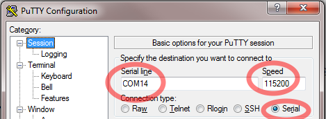
Beginning with version4.6.2a fix provides also direct access for Windows.PuTTY: A Free Telnet/SSH Client
- http://www.chiark.greenend.org.uk/~sgtatham/putty
- @GSI: use the "Softwarecenter" to install Putty.
- you have to find out which COM port the HadCon2 is connected to: e.g.
COM14- e.g. "Windows+R" → "devmgmt.msc" → (COM & LPT), before and after connecting HadCon2
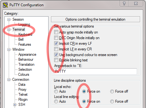
- settings:
- basic options:
- connection options:

- terminal options:
- basic options:
- then open a serial session to the COM port, e.g.
COM14
LabVIEW
- LabVIEW 2013 Instrument Driver
- try putty first to check basic communication
-- PeterZumbruch - 2020-11-10Protocol
General
- Structure
-
<Keyword, 3-5 letters, (capital letters)> <Message> - NOTE: from version 4.6.1 on all command keywords are case insensitive
- string termination (automatically) by <LF> or <CR>
-
RECVfollowed by the sent command keyword and the 'result' - nothing, usually send actions
- can be made more verbose by increasing the debug level via
DEBG <debug level>, <debug level> > 0-
RECV<literal acknowledge>*
-
- can be made more verbose by increasing the debug level via
-
ERRxin case of an error-
ERRx <Error number> <Error description> -
ERRx <Error number> <Error description> *** "<Additional Information>" -
ERRx "<Command>" <Error number> <Error description> -
ERRx "<Command>" <Error number> <Error description> *** "<Additional Information>" - where 'x' can be
-
G: global errors -
A: api errors, e.g. typos, wrong arguments, inputs, syntax, out of limits, etc. -
C: CAN related global errors -
M: CAN related message box errors -
T: I²C errors, Two-Wire-Interface -
U: undefined
-
-
CPU → μController
The communication consists of short command keywords, e.g.HELP,SEND,SPI, etc, followed by (optional) arguments or sub commandsμController → CPU
The following answers can occur
HELP
$HELP: will give an overview list of available commands, e.g. :
A more detailed command description you'll get by using the command:RECV HELP --- available commands are: RECV HELP --- SEND : send can message RECV HELP --- SEND CAN-ID ID-Range [RTR <nBytes> D0 .. D7] RECV HELP --- SUBS : unsubscribe can id/mask RECV HELP --- SUBS CAN-ID ID-Range RECV HELP --- USUB : unsubscribe can id/mask RECV HELP --- USUB CAN-ID ID-Range RECV HELP --- RGWR : write register RECV HELP --- RGWR <Register> <Value> RECV HELP --- RGRE : read register RECV HELP --- RGRE <Register> RECV HELP --- RADC : AVR ADCs RECV HELP --- RADC [<ADC Channel>] RECV HELP --- OWAD : 1-wire ADC RECV HELP --- OWAD [ID [flag_conv [flag_init]]] RECV HELP --- OWDS : 1-wire double switch RECV HELP --- OWDS [ID] RECV HELP --- INIT : (re)init of system RECV HELP --- OWLS : 1-wire list devices RECV HELP --- OWLS [<Family Code>] RECV HELP --- OWSS : 1-wire single switch ([ID] not implemented) RECV HELP --- OWSS [ID] RECV HELP --- RSET : reset via watchdog RECV HELP --- PING : RECV HELP --- OWTP : 1-wire temperature RECV HELP --- OWTP [ID [flag_conv [flag_init]] RECV HELP --- OWTP <command_keyword> [arguments]] RECV HELP --- OWSP : one-wire set active pins/bus mask RECV HELP --- OWSP <bus mask> RECV HELP --- CANT : CAN send message RECV HELP --- CANT CAN-ID ID-Range [RTR <nBytes> D0 .. D7] RECV HELP --- CANS : CAN subscribe RECV HELP --- CANS CAN-ID ID-Range RECV HELP --- CANU : CAN unsubscribe RECV HELP --- CANU CAN-ID ID-Range RECV HELP --- DBGL : set/get debug level RECV HELP --- DBGL [level] RECV HELP --- DBGM : set/get debug system mask RECV HELP --- DBGM [mask] RECV HELP --- JTAG : set/get JTAG availability, switch off/enable 4 more ADC channels RECV HELP --- JTAG [0|1] RECV HELP --- HELP : help RECV HELP --- HELP [CMND] RECV HELP --- HELP <mode> RECV HELP --- OWRP : 1-wire read active pins/bus mask RECV HELP --- DEBG : set/get debug level and mask RECV HELP --- DEBG [level [mask]] RECV HELP --- PARA : parasitic device presence test RECV HELP --- SHOW : show (internal) settings RECV HELP --- SHOW [key_word] RECV HELP --- OWSA : 1-wire API settings RECV HELP --- OWSA <command_key_word> [arguments] RECV HELP --- TWIS : I2C access RECV HELP --- TWIS <0|1> <I2C address> <data length> <byte1 ... byte8> RECV HELP --- I2C : I2C access RECV HELP --- I2C <0|1> <I2C address> <data length> <byte1 ... byte8> RECV HELP --- RLTH : relay threshold RECV HELP --- RLTH [command_key_word] <value> RECV HELP --- SPI : experimental SPI master (slave) RECV HELP --- SPI [data] RECV HELP --- SPI <cmd> <arguments> RECV HELP --- GNWR : waveform generator write data RECV HELP --- GNWR <address> <data> RECV HELP --- GNRE : waveform generator read data RECV HELP --- GNRE <address> RECV HELP --- OW8S : 1-wire octal switches RECV HELP --- OW8S [ID [value]] RECV HELP --- VERS : code versionHELP <command>
-- PeterZumbruch - 2020-11-09 - 12:09CAN
Keyword Action Format Description Comments SEND
CANTSend CAN Message SEND <CAN Message-ID> <ID-Range> [<RTR> <Length> <Data0 ... Data7>]
CANT<CAN Message-ID> <ID-Range> [<RTR> <Length> <Data0 ... Data7>]
response:
RECV<MOB-number> <CAN Message-ID> <ID-Range> [<RTR> <Length> <Data0 ... Data7>]
future response:
RECV<CAN Message-ID> <ID-Range> [<RTR> <Length> <Data0 ... Data7>]Message-ID: CAN Message Identifier (hex)
ID-Range: used as mask on Message IDs (hex)
RTR: sets Remote Transmission Request Mode
Length: number of data bytes to send (max: 8)
Data 0...7: 0 to 8 data bytes (hex) MOB-number: index of receiving MOB (Message Object Blocks) in CAN controllerSUBS
CANSSubscribe to Message-IDs SUBS <CAN Message-ID> <ID-Range>
CANS<CAN Message-ID> <ID-Range>
response:
nothingSubscribe to react on (a range of) CAN Messages
Message-ID: CAN Message Identifier (hex)
ID-Range: used as mask on Message IDs (hex)TODO: look to code, has to be clarified USUB
CANUUnsubscribe from Message-IDs USUB <CAN Message-ID> <ID-Range>
CANU<CAN Message-ID> <ID-Range>
response:
nothingUnsubscribe from reacting on (a range of) CAN Messages
Message-ID: CAN Message Identifier (hex)
ID-Range: used as mask on Message IDs (hex)TODO: look to code, has to be clarified CAN CAN commands CAN <sub command> [ <arguments>> ... ]
response:
...Replacing above commands by sub commoands TODO: -- PeterZumbruch - 2020-11-09 - 12:08SPI
- automatically ( Basic Operation ),
- semi-automatically ( Advanced Operation ), or
- manually ( Expert Operation )
- "Single Command Operation"
- All necessary steps are taken automatically, optional behavior can be achieved by changing the configuration.
- optionally purge read buffer
- (default
- TRUE)
- purge write buffer
- filling the write buffer
by decomposing input byte by byte
⇒dc 7f 8f 8f b4 01 23 45 67 89 ab cd ef be - set cs
- setting the defined chip-select pin(s) to "active low"
- optionally masked by an external mask
- setting the defined chip-select pin(s) to "active low"
- transmit/receive
byte by byte in the given byte-order- transmit write buffer content
- attaching received bytes to the end of the read buffer
- release cs
- release the defined chip-select pins(s) to "passive high"
- optionally masked by an external mask
- release the defined chip-select pins(s) to "passive high"
- optionally purge write buffer
(default: FALSE) - last read element
SPI read
- last read 3 elements
SPI show_read_buffer 3 1
- first read 6 elements
SPI show_read_buffer 6
- the full content
SPI show_read_buffer - set cs
- setting the defined chip-select pin(s) to "active low"
- optionally masked by an external mask
- setting the defined chip-select pin(s) to "active low"
- transmit/receive
byte by byte in the given byte-order- transmit write buffer content
- attaching received bytes to the end of the read buffer
- release cs
- release the defined chip-select pins(s) to "passive high"
- optionally masked by an external mask
- release the defined chip-select pins(s) to "passive high"
- optionally purge write buffer
- Format
-
-
SPI- short-cut of SPI status
-
- Format
-
-
SPI<list of data bytes|words|dwords|qwords>- short-cut of SPI write
-
- Task
- send list of bytes to clients, including predefined purge, chip-select behavior
- Format
-
-
SPI write<list of data bytes|words|dwords|qwords> -
SPI w<list of data bytes|words|dwords|qwords>
-
- Response
-
- nothing
- if
DEBG> 0RECV SPI write OK
- Description
-
As described in section Basic Operation- Arguments
-
- list of data bytes|words|dwords|qwords|...
- Comments
-
- Maximum single number length 24 digits
- only byte-wise sending allowed
- see SPI cs_select_mask
- see SPI auto_purge_write_buffer
- see SPI auto_purge_read_buffer
- see SPI transmit_report
- see SPI transmit_byte_order
- Task
- add list of data byte by byte to the write buffer
- Format
-
-
SPI add<list of data bytes|words|dwords|qwords> -
SPI a<list of data bytes|words|dwords|qwords>
-
- Response
-
- nothing
- if
DEBG> 0RECV SPI add OK
- Arguments
-
- list of data bytes|words|dwords|qwords|...
- Comments
-
- Maximum single number length 24 digits
- Task
- send write buffer content to clients, including predefined purge, chip-select behavior,
optionally selecting chip select pins - Format
-
-
SPI write_buffer[ <Chip Select Mask> ] -
SPI wb[ <Chip Select Mask> ]
-
- Response
-
RECV SPI write_buffer
- Description
-
- Arguments
-
- optional: external chip select mask:
- [ 0 ... FF]
- each bit represents a cs pin
- 1:active, 0:inactive
- optional: external chip select mask:
- Comments
- Task
- send write buffer content to clients, w/o any chip select manipulation
- Format
-
-
SPI transmit -
SPI t
-
- Response
-
- nothing
- if
DEBG> 0RECV SPI transmit OK
- Description
-
- Arguments
-
- -
- Comments
- Task
- sets (selected) chip select pins to "active low"
- Format
-
-
SPI cs_set[ <Chip Select Mask> ] -
SPI css[ <Chip Select Mask> ]
-
- Response
-
RECV SPI cs 1:1 2:- 3:- 4:- 5:- 6:- 7:- 8:-
- Description
- On success
csis called to show the current status- Arguments
-
- optional: external chip select mask:
- [ 0 ... FF]
- each bit represents a cs pin
- 1:active, 0:inactive
- optional: external chip select mask:
- Comments
-
- see SPI cs_select_mask
- see SPI cs
- Task
- releases (selected) chip select pins to "passive high"
- Format
-
-
SPI cs_release[ <Chip Select Mask> ] -
SPI csr[ <Chip Select Mask> ]
-
- Response
-
RECV SPI cs 1:1 2:- 3:- 4:- 5:- 6:- 7:- 8:-
- Description
-
- Arguments
-
- optional: external chip select mask:
- [ 0 ... FF]
- each bit represents a cs pin
- 1:active, 0:inactive
- optional: external chip select mask:
- Comments
-
- see SPI cs_select_mask
- see SPI cs
- Task
- read the last element filled into the read buffer
- Format
-
-
SPI read -
SPI r
-
- Response
-
RECV SPI read <value>
- Description
- read the last element filled into the read buffer
depending on the transmit_byte_order : * 0, MSB: last element (FIFO) * 1, LSB: first element (LIFO)- Arguments
-
- -
- Return values
-
-
<value>- "--" , if read buffer is empty
- last byte filled [0 .. FF]
-
- Comments
- Task
- show (partial) content of write buffer
- Format
-
-
SPI show_write_buffer[<Number of Bytes> [<Reverse Flag>]] -
SPI sw[<Number of Bytes> [<Reverse Flag>]]
-
- Response
-
- w/o any arguments,
buffer filled, ≤ 8 bytes:
 SPI sw
                  RECV SPI show_write_buffer elements: 0x5 (5)
RECV SPI show_write_buffer 10 00 10 21 42 - w/o any arguments,
buffer filled, > 8 bytes:
 SPI sw
                  RECV SPI show_write_buffer elements: 0x14 (20)
                  RECV SPI show_write_buffer (#1) 10 00 10 21 42 51 25 01 ...
                  RECV SPI show_write_buffer (#2) 10 10 10 00 10 21 42 51 ...
RECV SPI show_write_buffer (#3) 25 01 10 10 - w/
<Number of Bytes>set,<Number of Bytes>≠0,
buffer empty:
 SPI sw 3
RECV SPI show_write_buffer -- - w/
<Number of Bytes>set, e.g. 4,
buffer filled, ≤ 8 bytes:
 SPI sw 4
RECV SPI show_write_buffer 10 00 10 21 - w/
<Number of Bytes>set, e.g. 0xA,
buffer filled, > 8 bytes:
 SPI sw a
                  RECV SPI show_write_buffer (#1) 10 00 10 21 42 51 25 01 ...
RECV SPI show_write_buffer (#2) 10 10 - w/
<Number of Bytes>set, e.g. 2,
w/<Reverse Flag>flag set (TRUE,HIGH,ON,1)
buffer filled, ≤ 8 bytes,
 SPI sw 2 TRUE
RECV SPI show_write_buffer 10 10 - w/
<Number of Bytes>set, e.g. 9,
w/<Reverse Flag>flag set (TRUE,HIGH,ON,1)
buffer filled, > 8 bytes:
 SPI sw 9 1
                  RECV SPI show_write_buffer (#1) 00 10 21 42 51 25 01 10 ...
                  RECV SPI show_write_buffer (#2) 10
- w/o any arguments,
- Description
- Shows (partial) content of write buffer. Depending on the optional arguments the set can be reduced to a sub set of the buffer, beginning from the first element filled or reverse beginning with the last elements added. Depending on the number of elements requested, additional information is added:
- if all elements are show a summary line is added, with the given number of elements in the buffer in hex and decimal
- if the number of elements to show exceed
8- a line counter
(#i), starting from 1, is added in front - "..." are added at the end of the line, if more lines follow
- a line counter
- Arguments
-
-
<Number of Bytes>- max number of bytes to show, ≥ 0
-
0: all available - else: show
<Number of Bytes>elements from beginning (1) to maximum<Number of Bytes>
-
- max number of bytes to show, ≥ 0
-
<Reverse Flag>- flag to revert direction of interest
-
0,FALSE,OFF,LOW: show<Number of Bytes>elements from beginning (1) to maximum<Number of Bytes> - else: show
<Number of Bytes>elements from<number of elements> - <Number of Bytes>until last added element
-
- flag to revert direction of interest
-
- Comments
-
- -
- Task
- show (partial) content of read buffer
- Format
-
-
SPI show_read_buffer[<Number of Bytes> [<Reverse Flag>]] -
SPI sr[<Number of Bytes> [<Reverse Flag>]]
-
- Response
-
- w/o any arguments,
buffer filled, ≤ 8 bytes:
 SPI sr
                  RECV SPI show_read_buffer elements: 0x5 (5)
RECV SPI show_read_buffer 10 00 10 21 42 - w/o any arguments,
buffer filled, > 8 bytes:
 SPI sr
                  RECV SPI show_read_buffer elements: 0x14 (20)
                  RECV SPI show_read_buffer (#1) 10 00 10 21 42 51 25 01 ...
                  RECV SPI show_read_buffer (#2) 10 10 10 00 10 21 42 51 ...
RECV SPI show_read_buffer (#3) 25 01 10 10 - w/
<Number of Bytes>set,<Number of Bytes>≠0,
buffer empty:
 SPI sr 3
RECV SPI show_read_buffer -- - w/
<Number of Bytes>set, e.g. 4,
buffer filled, ≤ 8 bytes:
 SPI sr 4
RECV SPI show_read_buffer 10 00 10 21 - w/
<Number of Bytes>set, e.g. 0xA,
buffer filled, > 8 bytes:
 SPI sr a
                  RECV SPI show_read_buffer (#1) 10 00 10 21 42 51 25 01 ...
RECV SPI show_read_buffer (#2) 10 10 - w/
<Number of Bytes>set, e.g. 2,
w/<Reverse Flag>flag set (TRUE,HIGH,ON,1)
buffer filled, ≤ 8 bytes,
 SPI sr 2 TRUE
RECV SPI show_read_buffer 10 10 - w/
<Number of Bytes>set, e.g. 9,
w/<Reverse Flag>flag set (TRUE,HIGH,ON,1)
buffer filled, > 8 bytes:
 SPI sr 9 1
                  RECV SPI show_read_buffer (#1) 00 10 21 42 51 25 01 10 ...
                  RECV SPI show_read_buffer (#2) 10
- w/o any arguments,
- Description
- Shows (partial) content of read buffer. Depending on the optional arguments the set can be reduced to a sub set of the buffer, beginning from the first element filled or reverse beginning with the last elements added. Depending on the number of elements requested, additional information is added:
- if all elements are show a summary line is added, with the given number of elements in the buffer in hex and decimal
- if the number of elements to show exceed
8- a line counter
(#i), starting from 1, is added in front - "..." are added at the end of the line, if more lines follow
- a line counter
- Arguments
-
-
<Number of Bytes>- max number of bytes to show, ≥ 0
-
0: all available - else: show
<Number of Bytes>elements from beginning (1) to maximum<Number of Bytes>
-
- max number of bytes to show, ≥ 0
-
<Reverse Flag>- flag to revert direction of interest
-
0,FALSE,OFF,LOW: show<Number of Bytes>elements from beginning (1) to maximum<Number of Bytes> - else: show
<Number of Bytes>elements from<number of elements> - <Number of Bytes>until last added element
-
- flag to revert direction of interest
-
- Comments
-
- -
- Task
- purge write and read buffer
- Format
-
-
SPI purge -
SPI p
-
- Response
-
- nothing
- if
DEBG> 0RECV SPI purge OK
- Description
- purges write and read buffer, by internally calling
purge_write_bufferandpurge_read_buffer- Arguments
-
- -
- Comments
- Task
- purge write buffer
- Format
-
-
SPI purge_write_buffer -
SPI pw
-
- Response
-
- nothing
- if
DEBG> 0RECV SPI purge_write_buffer OK
- Description
-
- Arguments
-
- -
- Comments
-
- only resets the number of elements to 0, not the data
- Task
- purge read buffer
- Format
-
-
SPI purge_read_buffer -
SPI pr
-
- Response
-
- nothing
- if
DEBG> 0RECV SPI purge_read_buffer OK
- Description
-
- Arguments
-
- -
- Comments
-
- only resets the number of elements to 0, not the data
- Task
- resets SPI interface and SPI parameter settings to their default status
- Format
-
-
SPI reset
-
- Response
-
- nothing
- if
DEBG> 0RECV SPI reset OK
- Description
-
- Arguments
-
- -
- Comments
-
- see SPI status
- Task
- Show status
- Format
-
-
SPI status -
SPI s -
SPI
-
- Response
-
       RECV SPI status
      RECV SPI cs 1:0 2:- 3:- 4:- 5:- 6:- 7:- 8:-
      RECV SPI cs_bar 1:1 2:- 3:- 4:- 5:- 6:- 7:- 8:-
      RECV SPI cs_pins 1:PORTB,0
      RECV SPI cs_select_mask FF
      RECV SPI control_bits 50
      RECV SPI spi_enable TRUE
      RECV SPI data_order 0
      RECV SPI master TRUE
      RECV SPI clock_polarity 0
      RECV SPI clock_phase 0
      RECV SPI speed 0
      RECV SPI double_speed TRUE
      RECV SPI speed_divider 4 (2500000Hz @ 10000000Hz)
      RECV SPI transmit_byte_order 0 (MSB/big endian)
      RECV SPI transmit_report FALSE
      RECV SPI auto_purge_read_buffer TRUE
      RECV SPI auto_purge_write_buffer FALSE
      RECV SPI show_write_buffer elements: 0xd (13)
      RECV SPI show_write_buffer (#1) AB BB AA BB CC EE FF 66 ...
      RECV SPI show_write_buffer (#2) 54 12 45 54 58
RECV SPI show_read_buffer elements: 0 (0) - Description
-
- recursive call of all available status information
- Arguments
-
- -
- Comments
-
- -
- Task
- reports current status of (selected) chip select lines
- Format
-
-
SPI cs[<Chip Select Mask>]
-
- Response
-
- w/o mask
 SPI cs
                   RECV SPI cs 1:0 2:- 3:- 4:- 5:- 6:- 7:- 8:-
- w/ mask, eg.
0b01100001 = 0x71
 SPI cs 71
                   RECV SPI cs 1:0 6:- 7:-
- w/o mask
- Description
-
- Arguments
-
- optional
[<Chip Select Mask>]- [ 0 ... FF]
- each bit represents a cs pin
- 1:chosen, 0:ignore
- optional
- Response
-
- list of
<Pin States>- syntax
<Pin States>:-
<Index>:<State>-
<Index>:1 ... 8 -
<State>:-
1: HIGH -
0: LOW -
-: undefined, channel not connected
-
-
-
- syntax
- list of
- Comments
-
- -
- Task
- reports current inverted status of (selected) chip select lines
- Format
-
-
SPI cs_bar[<Chip Select Mask>] -
SPI csb[<Chip Select Mask>]
-
- Response
-
- w/o mask
 SPI csb
                   RECV SPI cs_bar 1:1 2:- 3:- 4:- 5:- 6:- 7:- 8:-
- w/ mask, eg.
0b01100001 = 0x71
 SPI csb 71
                   RECV SPI cs_bar 1:1 6:- 7:-
- w/o mask
- Description
-
- Arguments
-
- optional
<Chip Select Mask>- [ 0 ... FF]
- each bit represents a cs channel/pin
- 1:chosen, 0:ignore
- optional
- Response
-
- list of
<Pin States>- syntax
<Pin States>:-
<Index>:<State>-
<Index>:1 ... 8 -
<State>:-
1: LOW -
0: HIGH -
-: undefined, channel not connected
-
-
-
- syntax
- list of
- Task
- report current chip select channel configurations
- Format
-
-
SPI cs_pins[<CS Channel Index>]
-
- Response
-
- w/o argument
 SPI cs_pins
RECV SPI cs_pins <List of active <Index>:<PORTx>,<Pin> CS Configurations>- e.g.:
RECV SPI cs_pins 1:PORTB,0 2:PORTA,4 3:PORTG,4 7:PORTF,5
- e.g.:
- w/
<CS Channel Index>
SPI cs_pins<CS Channel Index>
RECV SPI cs_pins <Index><PORTx>,<Pin>,<Status>- e.g.:
 SPI cs_pins 1
                         RECV SPI cs_pins 1:PORTB,0,ON
- e.g.:
- w/o argument
- Description
-
- Arguments
-
- optional
<CS Channel Index>- chip select index
-
1 ... 8
- optional
- Return values
-
-
<List of active <Index>:<PORTx>,<Pin> CS Configurations>
or
<<Index>:<PORTx>,<Pin>,<Status> CS Configuration>-
<Index>- chip select index
-
1 ... 8
-
<PORTx>-
PORTx-
x:A ... G
-
-
-
<Pin>- pin number of
PORTx-
0 ... 7
-
- pin number of
-
<Status>- status of chosen chip select index
-
ON: active -
OFF: deactivated
-
- status of chosen chip select index
-
-
- Comments
-
- see SPI cs_add_pin
- see SPI cs_remove_pin
- Task
- get / set external chip select mask
- Format
-
-
SPI cs_select_mask[<Chip Select Mask>]
-
- Response
-
RECV SPI cs_select_mask <Value>
- Description
- The chip select mask allows to select a subset of the available, defined chip select channels.
Each bit of this mask represents a channel which can be selected or ignored.
This mask is used in all cases where chip select actions are required and not explicitly given.- w/o argument: the current mask is shown
- w/ argument:
<Value>is assigned to the configuration
- Arguments
-
- optional,
<Value>- chip select mask
- range
[0 ... FF] - each bit represents a chip select channel
- 1:chosen, 0:ignore
- optional,
- Comments
-
- -
- Task
- add chip select channel configuration
- Format
-
-
SPI cs_add_pin<Symbolic Output Port Address> <Output Port Pin> [<Channel Select Index/Slot>] -
SPI csap<Symbolic Output Port Address> <Output Port Pin> [<Channel Select Index/Slot>]
-
- Response
- see SPI cs_pins
RECV SPI cs_pins <List of active <Index>:<PORTx>,<Pin> CS Configurations> - Description
- Allows to add up to 8 output port
PORTX:Pincombinations to act as channel select channels. Provided the chosen slots aren't used yet or the address set is already defined (see SPI cs_pins, SPI cs_remove_pin).
A successful operation is reported via SPI cs_pins- w/o
<Channel Select Index/Slot>:- adds channel to next free slot
- w/
<Channel Select Index/Slot>:- adds channel to assigned index
- Arguments
-
-
<Symbolic Output Port Address> - symbolic name for the available output port addresses
-
PORTx-
x:A ... G
-
-
-
<Output Port Pin>- pin number of
PORTx-
0 ... 7
-
- pin number of
- optionally
<Channel Select Index/Slot>- chip select index
-
1 ... 8
-
- chip select index
-
- w/o
- Comments
-
- see SPI cs_pins
- see SPI cs_remove_pin
- Task
- remove chip select channel configuration
- Format
-
-
SPI cs_remove_pin<Channel Select Index/Slot> -
SPI csrp<Channel Select Index/Slot>
-
- Response
- see SPI cs_pins
RECV SPI cs_pins <List of active <Index>:<PORTx>,<Pin> CS Configurations> - Description
- Removes a chip select configuration from set of pin configuration (see SPI cs_pins).
A successful operation is reported via SPI cs_pins.- Arguments
-
-
<Channel Select Index/Slot>- chip select index
-
1 ... 8
-
- chip select index
-
- Comments
-
- see SPI cs_pins
- see SPI cs_add_pin
- Task
- set/get SPI hardware configuraton/status
- Format
-
-
SPI control_bits[<Extended SPI Control Register>] -
SPI c[<Extended SPI Control Register>]
-
- Response
- e.g. :
       RECV SPI control_bits 50
      RECV SPI spi_enable TRUE
      RECV SPI data_order 0
      RECV SPI master TRUE
      RECV SPI clock_polarity 0
      RECV SPI clock_phase 0
      RECV SPI speed 0
      RECV SPI double_speed TRUE
RECV SPI speed_divider 4 (2500000Hz @ 10000000Hz) - Description
- Allows to set/get the combined information/settings of the SPI Control Register
SPCRand the SPI Status RegisterSPSRen bloc. Therefore those two registers are combinded into one 16bit data word withSPCRas LSB andSPSRas MSB. SinceSPSR, despite its name, does have one control bit.
- w/o
<Extended SPI Control Register>:- reports status
- w/
<Extended SPI Control Register>:- changes configuration
- Note
- all settings can be done alone using the functions described below. Success is reported via its get mode and the get functions of the seperate properties.
- Arguments
-
-
<Extended SPI Control Register>-
0 ... 1FF
-
-
- w/o
- Comments
-
- See SPI spi_enable
- See SPI data order
- See SPI master
- See SPI clock polarity
- See SPI clock phase
- See SPI speed
- See SPI speed divider
- See SPI double speed
- Task
- get/set spi configuration's bit
SPI enable state: SPE - Format
-
-
SPI spi_enable[<value>]
-
- Response
-
RECV SPI spi_enable ==SPI enable state: SPE==
- Description
- "When the SPE bit is written to one, the SPI is enabled. This bit must be set to enable any SPI operation."
(from Manual: AT90CANxx)- w/o argument: get value
- w/ argument: set value
- Arguments
-
-
<value>-
0, 1, ≠0, ON, OFF, TRUE, FALSE
-
-
- Comments
-
- -
- Task
- get/set spi configuration's bit
SPI Data Order: DORD - Format
-
-
SPI data_order[<value>]
-
- Response
-
RECV SPI data_order
- Description
- "When the DORD bit is written to one, the LSB of the data word is transmitted first. When the DORD bit is written to zero, the MSB of the data word is transmitted first. "
(from Manual: AT90CANxx)- w/o argument: get value
- w/ argument: set value
- Arguments
-
-
<value>-
0, 1, ≠0, ON, OFF, TRUE, FALSE
-
-
- Comments
-
- Don't mix up with API's transmit_byte_order
- Task
- get/set spi configuration's bit
SPI Master/Slave Select: MSTR - Format
-
-
SPI master[<value>]
-
- Response
-
RECV SPI master
- Description
- "This bit selects Master SPI mode when written to one, and Slave SPI mode when written logic zero. If SS [the 'Chip Select Pin'] is configured as an input and is driven low while MSTR is set, MSTR will be cleared"
(from Manual: AT90CANxx)- w/o argument: get value
- w/ argument: set value
- Arguments
-
-
<value>-
(0,) 1, ≠0, ON, (OFF), TRUE, (FALSE)
-
-
- Comments
-
- Slave mode not implemented
- Task
- get/set spi configuration's bit
SPI Clock Polarity: CPOL - Format
-
-
SPI clock_polarity[<value>]
-
- Response
-
RECV SPI clock_polarity
- Description
- "When this bit is written to one, SCK is high when idle. When CPOL is written to zero, SCK is low when idle."
(from Manual: AT90CANxx)-
CPOL Leading Edge Trailing Edge 0 Rising Falling 1 Falling Rising - w/o argument: get value
- w/ argument: set value
- Arguments
-
-
<value>-
0, 1, ≠0, ON, OFF, TRUE, FALSE
-
-
-
- Comments
-
- -
- Task
- get/set spi configuration's bit
SPI Clock Phase: CPHA - Format
-
-
SPI clock_phase[<value>]
-
- Response
-
RECV SPI clock_phase
- Description
- "The settings of the Clock Phase bit (CPHA) determine if data is sampled on the leading (first) or trailing (last) edge of SCK."
(from Manual: AT90CANxx)CPHA Leading Edge Trailing Edge 0 Sample Setup 1 Setup Sample - w/o argument: get value
- w/ argument: set value
- Arguments
-
-
<value>-
0, 1, ≠0, ON, OFF, TRUE, FALSE
-
-
- Comments
-
- -
- Task
- get/set spi configuration's bits
SPI Clock Rate Select 1/0: SPR1/0 - Format
-
-
SPI speed[<value>]
-
- Response
-
RECV SPI speed
- Description
- "These two bits control the SCK rate of the device configured as a Master. SPR1 and SPR0 have no effect on the Slave. "
(from Manual: AT90CANxx)- w/o argument: get value
- w/ argument: set value
- Arguments
-
-
<value>-
0 ... 3 -
speed double speed clock rate: SCK frequency 0OFFfclkIO/4 1OFFfclkIO/16 2OFFfclkIO/64 3OFFfclkIO/128 0ONfclkIO/2 1ONfclkIO/8 2ONfclkIO/32 3ONfclkIO/64
-
-
- Comments
-
- See SPI double speed
- Task
- get/set spi configuration's
Clock Rate Divider - Format
-
-
SPI speed_divider[<value>]
-
- Response
-
RECV SPI speed_divider
- Description
- Set the ratio between fclkIO and
SCK frequency- w/o argument: get value
- w/ argument: set value
- Arguments
-
-
<value>-
2, 4, 8, 0x10, 0x20, 0x40, 0x80
-
-
- Comments
-
- See SPI speed
- See SPI double speed
- Task
- get/set spi configuration's bit
SPI Double Speed Bit: SPI2X - Format
-
-
SPI double_speed[<value>]
-
- Response
-
RECV SPI double_speed
- Description
- "When this bit is written logic one the SPI speed (SCK Frequency) will be doubled when the SPI is in Master mode. This means that the minimum SCK period will be two CPU clock periods. When the SPI is configured as Slave, the SPI is only guaranteed to work at fclkio/4 or lower."
(from Manual: AT90CANxx)- w/o argument: get value
- w/ argument: set value
- Arguments
-
-
<value>-
0, 1, ≠0, ON, OFF, TRUE, FALSE
-
-
- Comments
-
- -
- Task
- get/set the transmit order the data bytes of the buffer are written to the devices
- Format
-
-
SPI transmit_byte_order[<value>]
-
- Response
-
RECV SPI transmit_byte_order
- Description
-
- w/o argument: get value
- w/ argument: set value
- Arguments
-
-
<value>-
0, 1
<value> transmit byte order 0 MSB, big endian, FIFO 1 LSB, little endian, LIFO
-
-
- Comments
-
- -
- Task
- get status of / enable/disable additional transmission reports after sending the write buffer
- Format
-
-
SPI transmit_report[<value>]
-
- Response
- $ Description:
RECV SPI transmit_report
- w/o argument: get value
- w/ argument: set value
- Arguments
-
-
<value>-
0, 1, ≠0, ON, OFF, TRUE, FALSE
-
-
- Comments
-
- -
- Task
- get status of / enable/disable automatic write buffer purge after sending its content
- Format
-
-
SPI auto_purge_write_buffer[<value>]
-
- Response
- $ Description:
RECV SPI auto_purge_write_buffer
- w/o argument: get value
- w/ argument: set value
- Arguments
-
-
<value>-
0, 1, ≠0, ON, OFF, TRUE, FALSE
-
-
- Comments
-
- -
- Task
- get status of / enable/disable automatic read buffer purge before sending data
- Format
-
-
SPI auto_purge_read_buffer[<value>]
-
- Response
- $ Description:
RECV SPI auto_purge_read_buffer
- w/o argument: get value
- w/ argument: set value
- Arguments
-
-
<value>-
0, 1, ≠0, ON, OFF, TRUE, FALSE
-
-
- Comments
-
- -
Api Basic Operation Principle
General Operation
TheSPIcommand set allows to operate the Serial Peripheral Interface SPI interface of the HadCon(2)'s microcontroller, (currently "only") as a master. It sends data in atomic chunks of bytes via theMOSIpin to slave devices and receives via theMISOpin the responses. This happens in a buffered mode, so that multiple bytes can be send and received at once.
The current limitation of the write-buffer is linked to the input string buffer of 140 characters, i.e. ≈ 60 bytes. Up to 8 Chip-Select/SlaveS Select output pin(s) can be defined and manipulated eitherBasic Operation
equivalent toSPI write dc 7f 8f8fb4 0123456789abcdef be
NOTE: only even number of digits per argument are allowed ThisSPI dc 7f 8f8fb4 0123456789abcdef bewritecommand includes the following steps:
TheSPI purge_read_buffer// optionallySPI purge_write_buffer// optionallySPI add dc 7f SPI add 8f8fb4// repeat until write buffer is fullSPI add 0123456789abcdef//SPI add be//SPI show_write_buffer// optionallySPI write_buffer SPI write_buffer// e.g. repeat it, if auto_purge is OFFSPI write_buffer 02// only activate second chip select pin, by masking it with 0x02write_buffercommand includes all remaining necessary steps:
Reading: see Basic OperationSPI write dc 7f 8f8fb4 0123456789abcdef be SPI write_buffer// e.g. repeat it, if auto_purge is OFF... SPI write_buffer SPI write_buffer 02// only activate 2nd chip select pin, by masking it with 0x02SPI write_buffer 01// only activate 1st chip select pinSPI write_buffer fc// only activate the other chip select pins
Expert Operation
-
The user has full control on setting and releasing chip select pins.
Example sequence: selected chip select
Reading: see Basic OperationSPI purge_read_buffer// optionallySPI purge_write_buffer// optionallySPI add dc 7f 8f8fb4 0123456789abcdef be SPI cs// get status of defined chip select pinsSPI cs_bar// same as above but with "active low" logicSPI cs_set// set all available chip select pins to "active"SPI transmit SPI cs_release// set all available chip select pins to "passive"SPI cs_set 01// only activate 1st chip select pin to "active"SPI transmit SPI cs_release// set all available chip select pins to "passive"SPI cs_set fe// only activate the other chip select pins to "active"SPI transmit SPI cs_release ee// set masked chip select pins to "passive", keep 5th "active"SPI cs_release 10// set masked chip select pins to "passive", keep 5th "active"
Main Commands
SPI
SPI w/write
SPI a/add
SPI wb/write_buffer
SPI t/transmit
SPI css/cs_set
SPI csr/cs_release
SPI r/read
SPI sw/show_write_buffer
SPI sr/show_read_buffer
Clean-up
SPI p/purge
SPI pw/purge_write_buffer
SPI pr/purge_read_buffer
SPI reset
Status
SPI s/status
SPI cs
SPI csb/cs_bar
SPI cs_pins
Chip Select Configuration
SPI cs_select_mask
SPI csap/cs_add_pin
SPI csrp/cs_remove_pin
SPI Configuration
SPI c/control_bits
SPI spi_enable
SPI data_order
SPI master
SPI clock_polarity
SPI clock_phase
SPI speed
SPI speed_divider
SPI double_speed
API Configuration
SPI transmit_byte_order
SPI transmit_report
SPI auto_purge_write_buffer
SPI auto_purge_read_buffer
-- PeterZumbruch - 2020-11-09 - 12:15DAC
-
DAC: return all DACs value -
DAC <CHANNEL>: return current DAC value- <CHANNEL>: 0 - 7
- <CHANNEL>: 0 - 7
-
DAC: <CHANNEL> <VALUE_mV>: set current DAC output to (approx.) wanted voltage- <CHANNEL>: 0 - 7
- <VALUE_mV> - 0 - 3300 mV
-
 : The actual resulting value might differ, due to the 8bit conversion binning of 3300mV / 255 ≈ 12,94 mV
-
-
<CHANNEL>: 0 - 7 -
<VALUE_mV>: 0 - 3300 mV,undefined→ -1 -
<VALUE_HEX>: 0x00 - 0xFF,undefined→ 0x100 -
undefined: since there is no readback, values are undefined until a value is set,- exception: after a power up, channels are set to 0V.
Availablity
available since version: 4.6.3
Channel numbers
The Channel numbers 0..7 follow the signal naming (DACOUTx, q.v. HadCon2/DAC) and are therefore shifted by -1 compared to the connector pin numeration from pin 1 to pin 8. The remaining pin 9 and 10 are ground. (q.v. connector assignment)Commands
Output
-
The output is the same for all commands:
RECV DAC <CHANNEL> <VALUE_mV> <VALUE_HEX> [undefined]
withDAC, you will get the above for each channel from 0 to 7 in a separate line.
-- PeterZumbruch - 2020-11-09 - 12:16RGRE
RGRE <Register>
<Register> : the register has to be written with hexadecimal value
Example command:
send: RGRE d8
receive: RECV RGRE d8 2-- PeterZumbruch - 2020-11-09 - 12:05RGWR
Form:
RGWR <Register> <Value>
<Register> : the register address has to be written in hexadecimal<Value> : here has to be written the new register value in hexadecimal
Example command:
( toggling LEDs, by writing 1 to the PING0-PING5 registers while DDRG are set to outputs )
send: RGRE 32
(e.g.:)
receive: RECV RGRE 32 1c (11100)
send: RGWR 32 7
receive: RECV RGWR 7: value 1b has been written and readback does not match (1b)
(since PINs are outputs)
send: RGRE 32
receinve: RECV RGRE 32 1b-- PeterZumbruch - 2020-11-09 - 12:06I2C
Form:
I2C <0|1> <I2C address> <data length> <byte1 ... byte8><0|1> : used to execute write or read operation. This is the Least Significant Bit (LSB) from the I2C address byte.
<I2C address> : Here has to be written the hexadecimal value on the address byte, which is shifted to right with one bit. The reason for the right shift is because, the lsb bit ist already used in the first field, where the working operation is choosen. <data length> : data length <byte1 ... byte8> : data
Example command:
send: I2C 0 70 1 08
receive: RECV I2C 0 70 01 08 -OK--- PeterZumbruch - 2021-03-15 - 17:49
APFEL
- Logically
- Output:
-
CLK- quasi clock, only the level changes are important
-
DOUT- data out
-
Side Select- position
-
- Input:
-
DIN- data in
-
-
GND
- Output:
- Electrical:
- 3.3 Volt
- Physically:
- per default:
-
JDINOUT1/2, JADC- I/O ports:
I/O port A C F Connector JDINOUT1JDINOUT2JADCpins DIN11 DIN11 DIN11 DOUT12 DOUT12 DOUT12 CLK13 CLK13 CLK13 SS14 SS14 SS14 DIN25 DIN25 DIN25 DOUT26 DOUT26 DOUT26 CLK27 CLK27 CLK27 SS28 SS28 SS28
- I/O ports:
-
- per default:
- programm uses inline functions.
typical best measured "preHadCon2 Timings" ~× 8000 Clock Timing T [µs] 44.8 24.8 400,000 f [kHz] 22.3 40.3 0.0027 Function call overhead offset [µs] ~330 ~300 Task Timings Task typical best measured set DAC [ms] 2.4 1.4 read DAC [ms] 2.7 1.6 AutoCalibration [ms] 48.4 27 AutoCalibration × 256 × 2 [s] 24.8 13.8 TestPulseSequence [ms] 2.3 1.4 TestPulse [ms] 4.7 2.7 SetAmplitude [ms] 2.3 1.3 ResetAmplitude [ms] 2.3 1.3 - Task
- Format
-
- NOTE: setting
<chipId>to0xFFloops over all avaiable chip IDs - read
- single DAC at port/pos/chipId:
$CMND $command$ADDRESS <dacId>
- all 4 DACs at port/pos/chipId:
$CMND $command$ADDRESS
- all 4 DACs of all available chipIds at port/pos:
$CMND $command<portId> <sideSelectId>
- single DAC at port/pos/chipId:
- write
- single DAC at port/pos/chipIds:
$CMND $command$ADDRESS <dacId ≤ 4 > <value>
- all 4 DACs at port/pos/chipId with same value:
$CMND $command$ADDRESS <dacId > 4> <value>
- all 4 DACs at port/pos/chipId with individual values:
$CMND $command$ADDRESS <(dummy)> <valueDAC1> <valueDAC2> <valueDAC3> <valueDAC4>
- single DAC at port/pos/chipIds:
- NOTE: setting
- Response
-
- single dac channel access
RECV $CMND $command$ADDRESS <dacId> <value> - any other plots per found chip
RECV $CMND $command$ADDRESS <dacId> <valueDAC1> <valueDAC2> <valueDAC3> <valueDAC4>
- single dac channel access
- Description
-
read or write values from/to DAC channel(s) (if set with sign, incr/decr relatively)- Arguments
-
- <portId>
- <posId>
- <chipId>
- <dacId>
- <value>
- Comments
- Task
- Format
- Response
- Description
- Comments
- Task
- Format
- Response
- Description
- Comments
- Task
- Format
- Response
- Description
- Comments
- Task
- Format
- Response
- Description
- Comments
General Operation
TheAPFELcommand set allows to talk to (several instances of) the APFEL ASIC. It uses a subset of the the I/O-Ports of the ATMEL μController to facilitate the communication to the proprietary protocol (q.v.Decoder.pdf) of the asic, sending a 22bit sequence for command, value, and chipId. ( → Apfel protocol code sequences)
Version 0
In the run of development an intermediate short command set has been implemented which is not so well descriptive as its future successorCommands
task command individual arguments common address arguments comment setDac APFEL 9 <DAC value> <dac> <chipId> <pinSetId> <sideSelectId> <port> [<quiet>]
answer (if not quiet): → readDac<DAC value>
[ 0 ... 0x3FF ]
<DAC>
[ 1 ... 4 ]<chipId>
[ 0 ... 7, 8 ... FE, FF]
0xFF: generic call to all available chip Ids
<pinSetId>
[ 1, 2 ]
<sideSelectId>
[ 0,1 ]
<port>
A,C,F <quiet>
[0,1]writes DAC channel readDac APFEL A <dac> <chipId> <pinSetId> <sideSelectId> <port>
answers:
RECV APFEL dac <port> <pinSetId> <sideSelectId> <chipId> <dac> <DAC value>
ERRA APFEL dac <port> <pinSetId> <sideSelectId> <chipId> <dac> <DAC value> - read validity check failed, raw value:<DAC>
[ 1 ... 4 ]reads single DAC channel readAllDacs APFEL A 0 <chipId> <pinSetId> <sideSelectId> <port>
answers:
RECV APFEL dac <port> <pinSetId> <sideSelectId> <chipId> 0 <DAC value1> <DAC value2> <DAC value3> <DAC value4>
ERRA APFEL dac <port> <pinSetId> <sideSelectId> <chipId> <dac> <DAC value> - read validity check failed, raw value:*Not Yet Available* reads all DAC channels of an ch
autocalib APFEL B <chipId> <pinSetId> <sideSelectId> <port>auto calibration
TP single APFEL C <pulse height Pattern> <chipId> <pinSetId> <sideSelectId> <port><pulse height Pattern>
[ 2...3FF ]test pulse TP reset APFEL D <pulse height> <channel> <chipId> <pinSetId> <sideSelectId> <port><pulse height Pattern>
[ 1 ... F ]
<channel>
[ 1, 2 ]test pulse inkl. reset TP trigger APFEL 11 <on/off> <port> <pin> <trigger position><on/off>
[ 0,1 ]
<port>
[ A,B,C,D,E,F,G ]
<pin>
[1...8]
<trigger after set (1) or after reset (2)>
[1,2]<on/off> enables/disables <pin> on <port> to trigger right in the moment after a test pulse set or reset command sequence is sent
setAmpl APFEL E <channel> <chipId> <pinSetId> <sideSelectId> <port><channel>
[ 1, 2 ]setAmplification to high resetAmpl APFEL F <channel> <chipId> <pinSetId> <sideSelectId> <port><channel>
[ 1, 2 ]resetAmplification to low
listId APFEL 10 <all> <NChipIds> <pinSetId> <sideSelectId> <port><all flag>
[ 1...FF ] <number of chip Ids>
[ 1...FF ]check <number of chip Ids> channels and list depending on the <all flag> all or only positive results listId++ APFEL 20 <all> <NChipIds> <minChipId> <pinSetId> <sideSelectId> <port><all flag>
[ 1...FF ] <number of chip Ids>
[ 1...FF ] <min Chip Id>
[ 1...FF ]check <number of chip Ids> channels and list depending on the <all flag> all or only positive results
First Test Results (16 Jan 2015)
First Test Results from 16 Jan 2015
Logic Analyzer Results (14 Oct 2015)
Logic Analyzer Results
Summary (10 Oct 2015)
typical "preHadCon2 Timings" ~× 104 Clock Timing T [µs] 40 400,000 f [kHz] 25 kHz 0.0027 Function call overhead offset [µs] ~330 Task Timings Task typical set DAC w/o readback [ms] 2 read DAC [ms] 2.3 set DAC w/ readback (estimate) [ms] 4.3 AutoCalibration [ms] ~155 AutoCalibration × 256 × 2 (estimate) [s] ~80 TestPulseSequence [ms] 2 complete TestPulse [ms] 4 SetAmplitude [ms] 2 ResetAmplitude [ms] 2
Details (port A - 10 Oct 2015)
set DAC APFEL 9 3FF 3 1 1 1 A 1%FOREACH{"item" in="setDac_APFEL_9_3FF_3_1_1_1_A_1_2015-10-14.png"}% %NEXT{"item"}%
readDAC APFEL A 3 1 1 1 A%FOREACH{"item" in="readDac_APFEL_A_3_1_1_1_A_2015-10-14.png"}% autocalibration APFEL B 1 1 1 A%FOREACH{"item" in="autocalib_APFEL_B_1_1_1_A__2015-10-14.png"}% autocalibration (full) APFEL B 1 1 1 A%FOREACH{"item" in="autocalib_APFEL_B_1_1_1_A_(full)_2015-10-14.png"}% TP single APFEL C 3 1 1 1 A%FOREACH{"item" in="TP_single_APFEL_C_3_1_1_1_A_2015-10-14.png"}% TP reset ch1 APFEL D 9 1 1 1 1 A%FOREACH{"item" in="TP_reset_APFEL_D_9_1_1_1_1_A_2015-10-14.png"}% TP reset ch2 APFEL D 9 2 1 1 1 A%FOREACH{"item" in="TP_reset_APFEL_D_9_2_1_1_1_A_2015-10-14.png"}% TP reset ch1 incl. Trig, Pos 1 APFEL D 9 1 1 1 1 A%FOREACH{"item" in="TP_reset_inkl_Trig_Pos_1_APFEL_D_9_1_1_1_1_A_2015-10-14.png"}% TP reset ch1 incl. Trig, Pos 2 APFEL D 9 1 1 1 1 A%FOREACH{"item" in="TP_reset_inkl_Trig_Pos_2_APFEL_D_9_1_1_1_1_A_2015-10-14.png"}% set amplification APFEL E 2 1 1 1 A%FOREACH{"item" in="setAmplification_APFEL_E_2_1_1_1_A__2015-10-14.png"}% reset amplification APFEL F 2 1 1 1 A%FOREACH{"item" in="resetAmplification_APFEL_F_2_1_1_1_A_2015-10-14.png"}% Details (port F - 06 Nov 2015)
Trigger Level at 2.0Vset DAC APFEL 9 3FF 3 1 1 1 F 1%FOREACH{"item" in="setDac_APFEL_9_3FF_3_1_1_1_F_1_2015-11-06.png"}% readDAC APFEL A 3 1 1 0 F%FOREACH{"item" in="readDac_APFEL_A_3_1_1_0_F_2015-11-06.png"}% autocalibration APFEL B 1 1 1 F%FOREACH{"item" in="autocalib_APFEL_B_1_1_1_F_2015-11-06.png"}% TP single APFEL C 3 1 1 0 F%FOREACH{"item" in="TP_single_APFEL_C_3_1_1_0_F_2015-11-06.png"}% TP reset ch2 APFEL D 9 2 1 1 1 F%FOREACH{"item" in="TP_reset_APFEL_D_9_2_1_1_1_F_2015-11-06.png"}% set amplification APFEL E 2 1 1 0 F%FOREACH{"item" in="setAmplification_APFEL_E_2_1_1_0_F_2015-11-06.png"}% reset amplification APFEL F 2 1 1 1 F%FOREACH{"item" in="resetAmplification_APFEL_F_2_1_1_1_F_2015-11-06.png"}%
Version 1
not yet implemented, but you may have a look ...
%FOREACH{"ADDRESS" in="<portLetter> <portIndex> <sideSelectionId> <chipId>"}% %FOREACH{"CMND" in="APFEL"}%Overview
-
overall main command structure:
$CMND<command> $ADDRESS [<Argument(s)>]command address arguments comment "channel" value(s) dac<portLetter>
A,C,F,
<pinSetId>
[ 1, 2 ]<sideSelectId>
[ 1, 2 ]<chipId>
[ 0 ... 7, 8 ... FE, FF]
0xFF: generic call to all available chip Ids
see command chipIdIgnoreMask for limiting the chipId range<dacId>
[ 1 ... 4 ]
< 4, e.g.0xA: all DACs get value vDAC1[vDAC1[vDAC2[vDAC3[vDAC4]]]]
[ 0 ... 0x3FF ]read/writes up to 4 DAC channels (if set with sign, incr/decr relatively) autoCalibauto calibration of the DAC channels testPulse<channelId>
[ 1 ... 2 ]
< 4, e.g.0xA: both channelsheight1 [height2]
[ 0 ... 0xF ]initiate test pulse ampl<channelId>
[ 1 ... 2 ]
< 4, e.g.0xA: both channels[ amplification1 [amplification2] ]
[ 0,1, H,L ]
0,L: low amplification (× 16)
1,H: high amplification (× 32)get/set amplification mode l/listlists all addresses of available ids
%FOREACH{"command" in="dac"}% %FOREACH{"alternative" in="d"}%$CMND $alternative/$command
$CMND $alternative/$command
$CMND $alternative/$command
$CMND $command
$CMND $alternative/$command
%NEXT{"CMND"}% %NEXT{"ADDRESS"}%
-- PeterZumbruch - 2020-11-09-- PeterZumbruch - 2016-02-19
- Output settings:
Performance
Performance Tests
- The current firmwares (up to 4.6.2) all run at 10 MHz HadCon2 clock and
have 115200 kBits/s at the UART with 8N1 setting - Thus a long message of 100 Byte (maximum 140 Byte) would need at least:
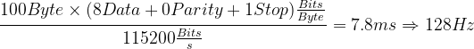
Message Length [Byte] approx. Duration [ms] max. Frequency [Hz] comment 140 10.9 91 max. message size incl. CR and LF 100 7.8 128 25 1.95 512 e.g. APFEL 9 300 3 1 1 A 1\r\n 12 0.94 1067 e.g. RGWR 2c f0\r\n - possible improvements:
- 10 MHz ⇒ 16 MHz would allow Bitrates up to 1 MBaud, i.e.
Message Length [Byte] approx. Duration [ms] max. Frequency [Hz] comment 140 1.26 793.7 max. message size incl. CR and LF 100 0.9 1111 25 0.225 4444 e.g. APFEL 9 300 3 1 1 A 1\r\n 12 0.108 9259 e.g. RGWR 2c f0\r\n
- 10 MHz ⇒ 16 MHz would allow Bitrates up to 1 MBaud, i.e.
- HadCon2
- Firmware Version: 4.6.3.APFEL May 27 2015 15:52
- 115200 kBit/s
- 10 MHz Clock
- Raspberry Pi B (1)
- EPICS
- base3.14.12.4
- streamDevice-2-6
- asyn4-23
- application:
- calcout Record using streamDevice and the protocol File RGWR.proto to send:
RGWR <register address> <value> - modified menuScan.dbd ⇒ menuScanFast.dbd to provide faster scan rates up to 1000kHz.
- hadcon2_RGWR_test.tar.bz2
- calcout Record using streamDevice and the protocol File RGWR.proto to send:
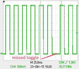
- toggle:
By sendingRGWR 2c 80, i.e. the PINE register, the 8th pin (PE7) onPORT Ewhich is connected partly to HadCon2's connectorJAtmelMisc1, pin no. 8, is toggling its state.
Connected to an oscilloscope the response - an rectangular pulse train - is measured. Two scenarios are measured:- normal operation of the IOC
- slowed down by streamDevice debug printouts -
var streamDebug 1
-
By sending alternatingly
RGWR 2e 80orRGWR 2e 0, i.e. the PORTE register, the 8th pin (PE7) onPORT Ewhich is connected partly to HadCon2's connectorJAtmelMisc1, pin no. 8, is actively written 0/1 to.
Connected to an oscilloscope the response - an rectangular pulse train - is measured. - RGWR-perfomance-toggle.xlsx: Excel Sheet Measurements
- For a simple toggling register, the maximum frequency is between:
- 66.67 Hz and 71.43 Hz.
- Thus the recommendation is to stay above a corresponding EPICS SCAN time of:
- 0.015s
- If any streamDebug features are active, i.e. print outs to screen, the performance is reduced by:
- a factor of 10
- at higher SCAN rates up to 80% of the toggle signals are lost, but the system is still performing, since the commands are always the same.
- in those cases the ratios show that the actual scan time is scaled up.
- other cases have not been investigated
- RGWR toggle performance ratios:
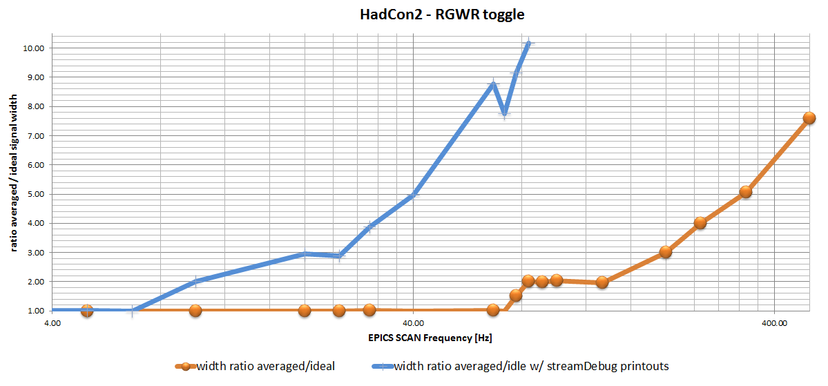
- finally at a rate of 1kHz, the system reaches is limit and the communication to the board ceases, but can be recovered.
- For a set/reset register, the maximum frequency is at around:
- 60 Hz.
- Thus the recommendation is to stay above a corresponding EPICS SCAN time of:
- 0.017s
Theoretical limits
Rate stability - RGWR toggle I/O port
Setup
Procedures
Measurements
Data: toggle
| EPICS SCAN rate | Freq [Hz] (1/SCAN) | ideal width | w/o streamDebug output | w/ streamDebug printouts | ||||||||||||
|---|---|---|---|---|---|---|---|---|---|---|---|---|---|---|---|---|
| Freq [Hz] of 2 Triggers | W: averaged signal width [ms] | ΔW [ms] | ΔW/W | width ratio averaged/ideal | Lost Triggers/Triggers | relative Loss | Freq [Hz] of 2 Triggers | W: averaged signal width [ms] | ΔW [ms] | ΔW/W | width ratio averaged/ideal | Lost Triggers/Triggers | relative Loss | |||
| 2.00 | 0.50 | 2000 | 0.250 | 2000.0 | 80 | 4.0% | 1.00 | 0/50 | 0.0% | 0.25 | 2000 | 85 | 4.3% | 1.0 | 0/25 | 0.0% |
| 1.00 | 1.00 | 1000 | 0.500 | 1000.0 | 40 | 4.0% | 1.00 | 0/50 | 0.0% | 0.5 | 1000 | 40 | 4.0% | 1.0 | 0/25 | 0.0% |
| 0.50 | 2.00 | 500 | 1.000 | 500.1 | 35 | 7.0% | 1.00 | 0/50 | 0.0% | 1 | 500 | 21 | 4.2% | 1.0 | 0/11 | 0.0% |
| 0.20 | 5.00 | 200 | 2.500 | 200.0 | 10 | 5.0% | 1.00 | 0/50 | 0.0% | 2.475 | 202 | 13 | 6.4% | 1.0 | 0/25 | 0.0% |
| 0.15 | 6.67 | 150 | 3.378 | 148.0 | 5 | 3.4% | 0.99 | 0/67 | 0.0% | 3.333 | 150 | 9 | 6.0% | 1.0 | 0/17 | 0.0% |
| 0.1 | 10.00 | 100 | 5.000 | 100.0 | 6 | 6.0% | 1.00 | 0/50 | 0.0% | 2.5 | 200 | 4 | 2.0% | 2.0 | 13/25 | 52.0% |
| 0.05 | 20.00 | 50 | 10.000 | 50.0 | 3 | 6.0% | 1.00 | 0/50 | 0.0% | 3.378 | 148 | 5 | 3.4% | 3.0 | 13/20 | 65.0% |
| 0.04 | 25.00 | 40 | 12.500 | 40.0 | 4 | 10.0% | 1.00 | 0/63 | 0.0% | 4.348 | 115 | 5 | 4.3% | 2.9 | 17/25 | 68.0% |
| 0.033 | 30.30 | 33 | 14.900 | 33.6 | 3 | 8.9% | 1.02 | 0/76 | 0.0% | 3.9 | 128 | 12 | 9.4% | 3.9 | 22/30 | 72.6% |
| 0.025 | 40.00 | 25 | 20.160 | 24.8 | 1 | 4.0% | 0.99 | 0/21 | 0.0% | 4.032 | 124 | 10 | 8.1% | 5.0 | 32/40 | 80.0% |
| 0.015 | 66.67 | 15 | 32.900 | 15.2 | 1 | 6.6% | 1.01 | 0/67 | 0.0% | 3.8 | 132 | 2 | 1.5% | 8.8 | 58/67 | 87.0% |
| 0.014 | 71.43 | 14 | 35.720 | 14.0 | 3.5 | 25.0% | 1.00 | 3.5/72 | 4.9% | 4.6 | 109 | 5 | 4.6% | 7.8 | 62/71 | 86.8% |
| 0.013 | 76.92 | 13 | 25.300 | 19.8 | 8 | 40.5% | 1.52 | 23/100 | 23.0% | 4.2 | 119 | 1 | 0.8% | 9.2 | 68/77 | 88.4% |
| 0.012 | 83.33 | 12 | 20.830 | 24.0 | 3 | 12.5% | 2.00 | 52/105 | 49.5% | 4.1 | 122 | 2 | 1.6% | 10.2 | 74/83 | 88.8% |
| 0.011 | 90.91 | 11 | 23.000 | 21.7 | 1 | 4.6% | 1.98 | 44/90 | 48.9% | |||||||
| 0.01 | 100.00 | 10 | 24.500 | 20.4 | 0.5 | 2.5% | 2.04 | 50/100 | 50.0% | |||||||
| 0.0075 | 133.33 | 7.5 | 33.800 | 14.8 | 2 | 13.5% | 1.97 | 33/66 | 50.0% | |||||||
| 0.005 | 200.00 | 5 | 33.330 | 15.0 | 2 | 13.3% | 3.00 | 67/100 | 67.0% | |||||||
| 0.004 | 250.00 | 4 | 31.200 | 16.0 | 2 | 12.5% | 4.01 | 93/125 | 74.4% | |||||||
| 0.003 | 333.33 | 3 | 33.000 | 15.2 | 2 | 13.2% | 5.05 | 133/166 | 80.1% | |||||||
| 0.002 | 500.00 | 2 | 32.900 | 15.2 | 1 | 6.6% | 7.60 | 267/333 | 80.2% | |||||||
| 0.001 | 1000 | 1 | breakdown of communication via UART, close to theoretical limit of ≈ 1kHz | |||||||||||||
Data: set/reset
| EPICS SCAN rate | Freq [Hz] (1/SCAN) | ideal width | Freq [Hz] of 2 Triggers | W: averaged signal width [ms] | ΔW [ms] | ΔW/W | width ratio averaged/ideal | Lost Triggers/Triggers | relative Loss |
|---|---|---|---|---|---|---|---|---|---|
| 1,00 | 1,00 | 1000 | 0,500 | 1000,0 | 10 | 1,0% | 1,00 | 0/10 | 0,0% |
| 0,50 | 2,00 | 500 | 1,000 | 500,0 | 22 | 4,4% | 1,00 | 0/50 | 0,0% |
| 0,20 | 5,00 | 200 | 2,500 | 200,0 | 10 | 5,0% | 1,00 | 0/50 | 0,0% |
| 0,15 | 6,67 | 150 | 3,200 | 156,3 | 15 | 9,6% | 1,04 | 0/60 | 0,0% |
| 0,10 | 10,00 | 100 | 5,000 | 100,0 | 5 | 5,0% | 1,00 | 0/100 | 0,0% |
| 0,03 | 30,30 | 33 | 15,430 | 32,4 | 0,4 | 1,2% | 0,98 | 0/30 | 0,0% |
| 0,03 | 40,00 | 25 | 20,000 | 25,0 | 1,5 | 6,0% | 1,00 | 0/100 | 0,0% |
| 0,02 | 66,67 | 15 | 33,330 | 15,0 | 1,1 | 7,3% | 1,00 | 3/166 | 1,8% |
| 0,01 | 71,43 | 14 | 35,715 | 14,0 | 1 | 7,1% | 1,00 | 14/71 | 19,7% |
| 0,01 | 76,92 | 13 | 37,600 | 13,3 | 1 | 7,5% | 1,02 | 30/76 | 39,5% |
| 0,01 | 83,33 | 12 | 10,000 | 50,0 | 5 | 10,0% | 4,17 | 194/208 | 93,3% |
Results
RGWR toggle performance:

RGWR set/reset performance:

-- PeterZumbruch - 2020-11-09
-- PeterZumbruch - 2020-08-04
Please login to edit this topic
Topic revision: r28 - 2020-11-09, PeterZumbruch
- User Reference
- BeginnersStartHere
- EditingShorthand
- Macros
- MacrosQuickReference
- FormattedSearch
- QuerySearch
- DocumentGraphics
- SkinBrowser
- InstalledPlugins
- Admin Maintenance
- Reference Manual
- AdminToolsCategory
- InterWikis
- ManagingWebs
- SiteTools
- DefaultPreferences
- WebPreferences
- Categories
Ideas, requests, problems regarding GSI Wiki? Send feedback | Legal notice | Privacy Policy (german)