|
|
You are here: GSI Wiki>TOS/Timing Web>TimingSystemDocumentation>TimingSystemDocuments>TimingSystemRelease>TimingSystemNodesReleaseAsterisk>TimingSystemNodesReleaseAsteriskPexaria5Commission (2017-12-05, dbeck)
Step-by-step guide to commissioning a new pexaria5:
- Place powered-off pexaria5 on ESD-desk , ESD dischare!
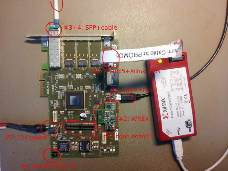
- Attach wrex2a addon board to baseboard WR1 (WREX2a benötigt ca. 70mA mehr als WREX1)
- Insert green SFP into baseboard cage
- Connect SFP to WR network
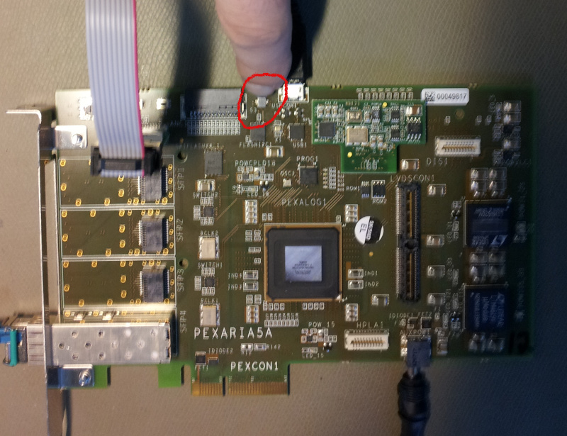
- Connect USBCON1 to PC
- Remove any pexaria5dbx addon board, bzw. Abstandshalter angeschraubt?
- Attach power via 12V input plug (don't power the board yet, just attach the cable), Current limit set to 1000mA
- Connect Xilinx programmer to JTAG
- Make sure the card has a serial# on it + Add CID-LABEL,

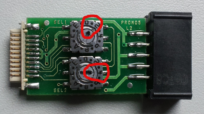
- Set promo5 adapter to SEL1=1, SEL2=4

- Open ISE with syn/gsi_pexarria5/cpld/pexaria5_prog.xise
- Process Menu => Implement Top Module
- Tools Menu => Impact
- Power-on pexaria5 ... then immediately (practice on a working pexaria first):
- Double-click Boundary Scan
- Control-I, prog1.jed
- Operations Menu => Program
- Power-off pexaria5
- Run 'make' in bel_projects/ip_cores/etherbone-core/hdl/eb_usb_core
- Download http://tsl002.acc.gsi.de/releases/cherry/gateware/ oder pexaria5-a2.sof.xz
- Decompress it with: 'xz -d pexaria5-a2.sof.xz'
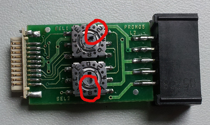
- Set promo5 to SEL1=2, SEL2=8

- Connect USB-Blaster to JTAG
- Power-on pexaria5 power ~
- Press and hold switch S3

- Run: quartus_pgm -c 1 -m jtag -o 'p;pexaria5-a2.sof'
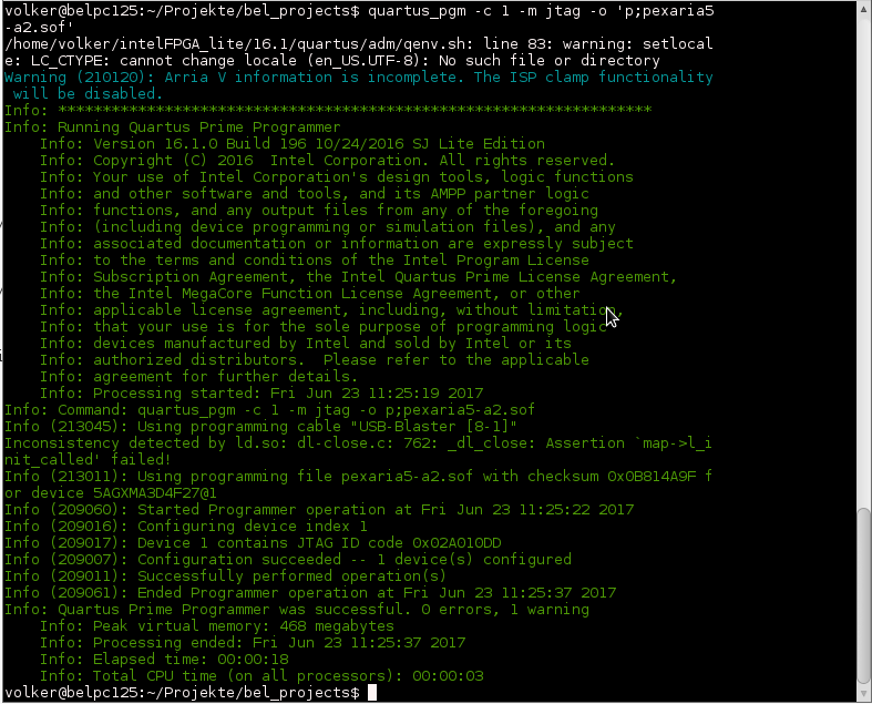
- Release S3 , lange warten -> ca. 20 sec bis grüner Text erscheint
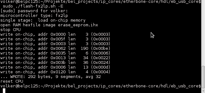
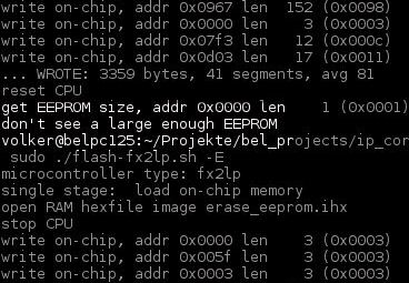
- Erase USB controller (as root): ./flash-fx2lp.sh -E
- Reprogram (reset) the pexaria5: quartus_pgm -c 1 -m jtag -o 'p;pexaria5-a2.sof'
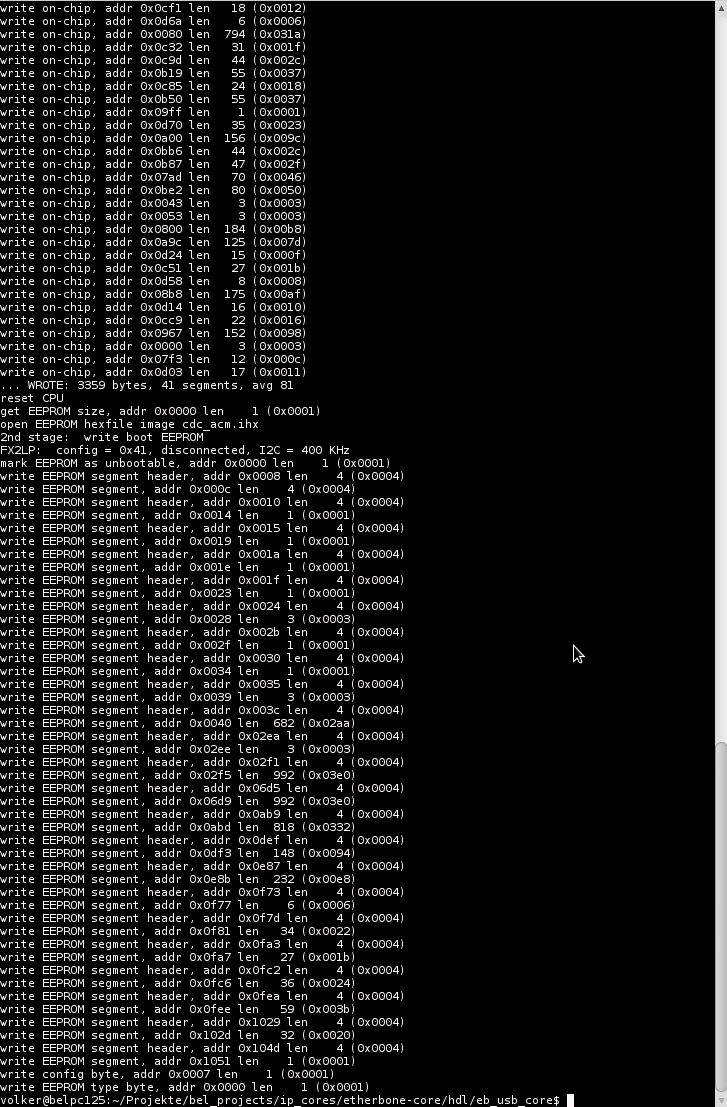
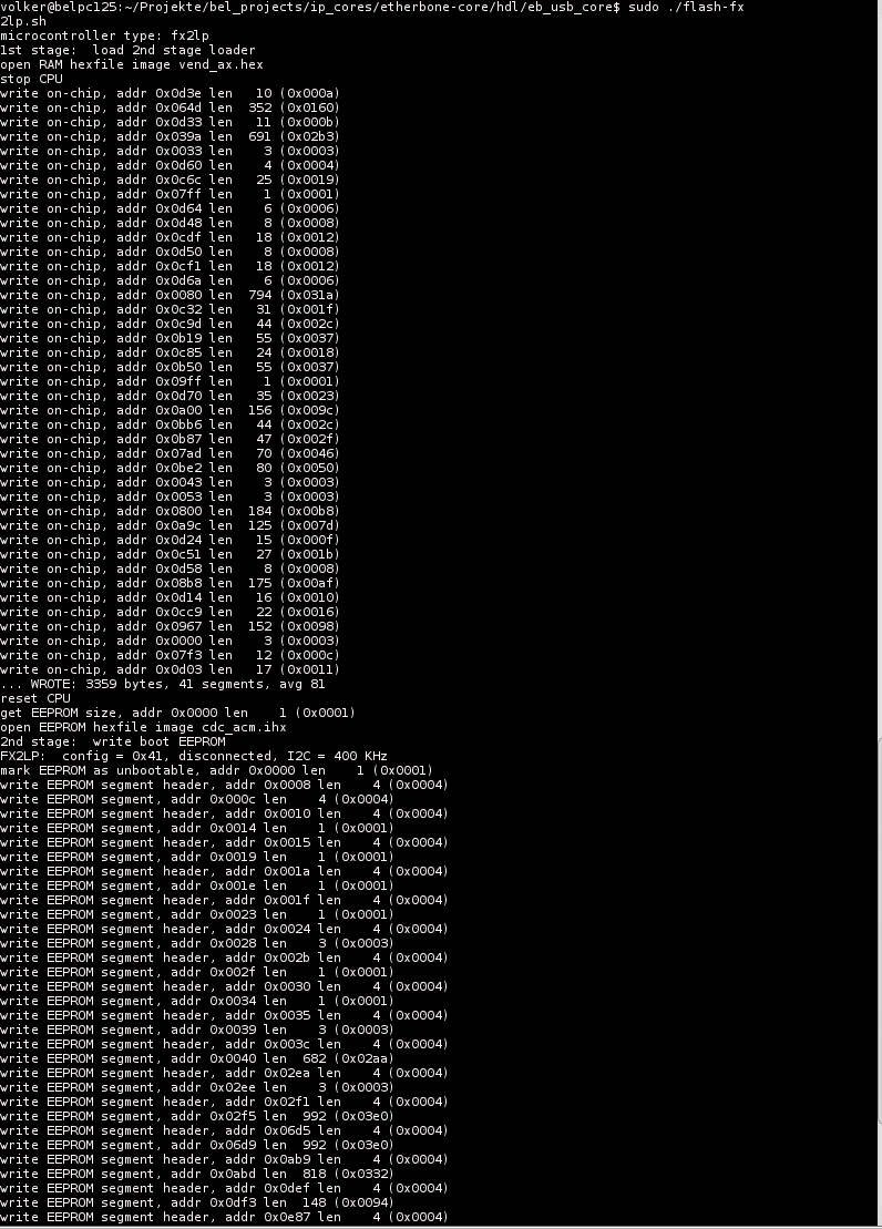
- Program the USB controller (as root): ./flash-fx2lp.sh Gelegentlich erscheint die Fehlermeldung "Don't see large enough EEPROM" und PROGRAM wird abgebrochen. Erase und Program sind dann zu wiederholen.
- Reprogram (reset) the pexaria5: quartus_pgm -c 1 -m jtag -o 'p;pexaria5-a2.sof'
- Configure the SPI flash chip: eb-config-nv dev/ttyUSBx 10 4, no response if all is ok

- Format the 1-wire EEPROM in bel_projects/ip_cores/wrpc-sw/tools: eb-w1-write dev/ttyUSBx 0 320 < sdb-wrpc.bin , no response if all is ok, cd ~/Projekte/bel_projects/ip_cores/wrpc-sw/tools | sudo ./eb-w1-write dev/ttyUSB0 0 320 < sdb-wrpc.bin
- Power-cycle the pexaria5 / Power ~ 480mA/12V
- Program the pexaria5: quartus_pgm -c 1 -m jtag -o 'p;pexaria5-a2.sof'
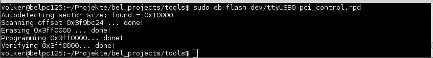
- Flash the FPGA; eb-flash dev/ttyUSBx pci_control.rpd
- Run eb-console dev/ttyUSBx
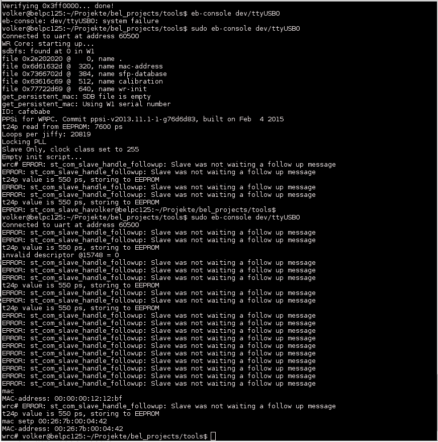
- Set MAC address for board #xy: mac setp 00:26:7b:00:04:xy, # exit with crtl-c
- Power off the FPGA, remove JTAG
- Attach addon board + Add CID Label
- Power on the FPGA Power ~530mA /12V, Mit WREX2A sind es ~ 600mA/12V
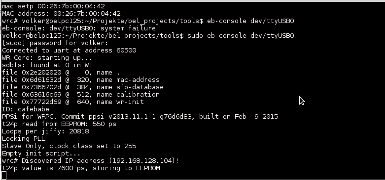
- Run eb-console dev/ttyUSBx
- Check 'gui' for Clock Offset <= 10ps for at least 30 seconds.
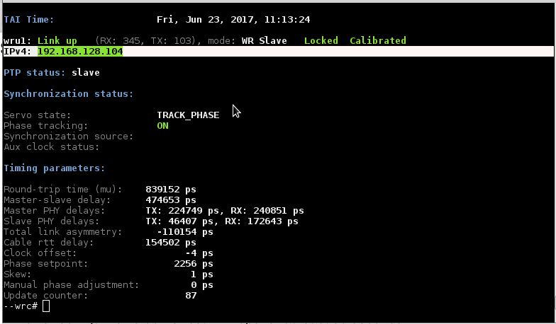
- Confirm that the card receives an IP address , - Erscheint rote IP Meldung BOOTP RUNNING ist die MAC Adresse nicht bekannt bzw. angemeldet. # exit with crtl-c
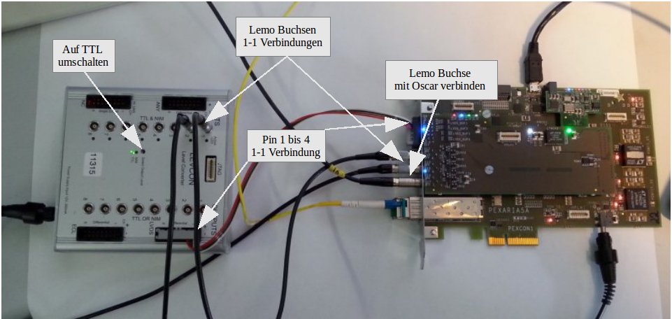
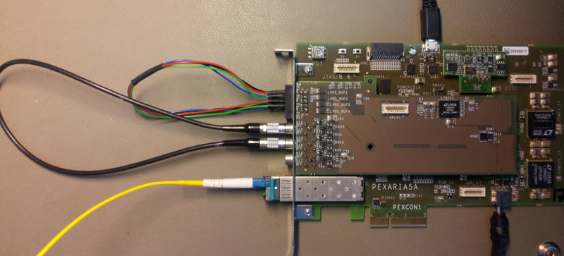
- Attach level Converter (see pic)
- Run bel_projects/tools/io-test dev/ttyUSBx
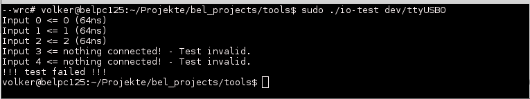
- Move cable to IO1 and IO3
- Rerun io-test
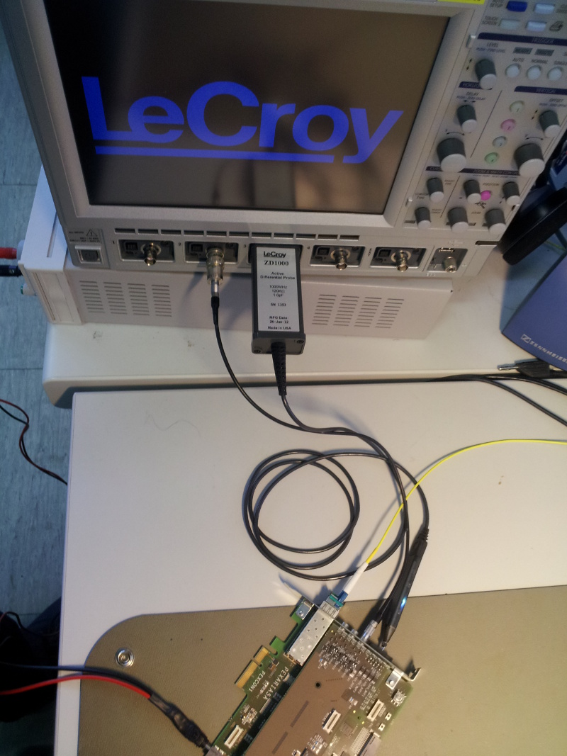
- Disconnect cables, and attach to scope

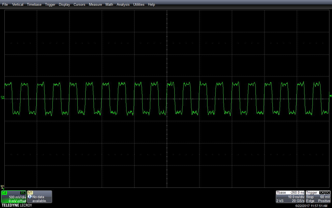
- Check voltage levels of all 3 LEMOs (0V...3V) and the LVDS (-0.4V...0.4V) outputs
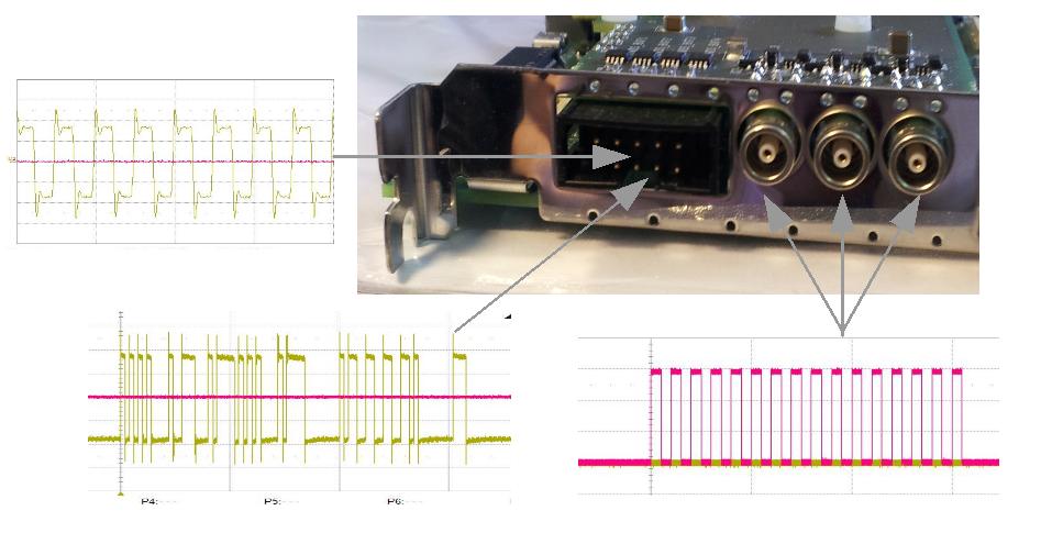
- Check 200Mhz at 2. connector
- Confirm all (4+4) LEDs blink as with the io-test and 2+4 blink to indicate WR network status
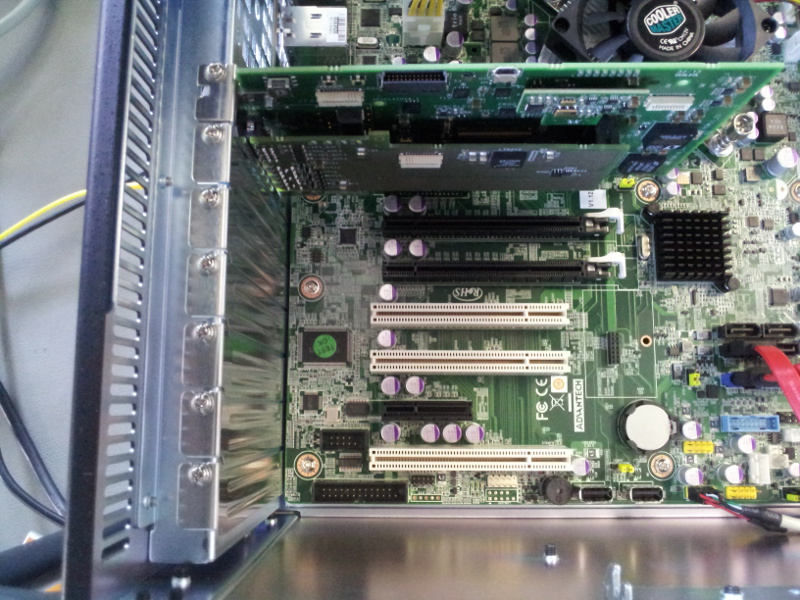
- Add Bracket + Insert card into a PC

- Run: eb-console dev/wbm0
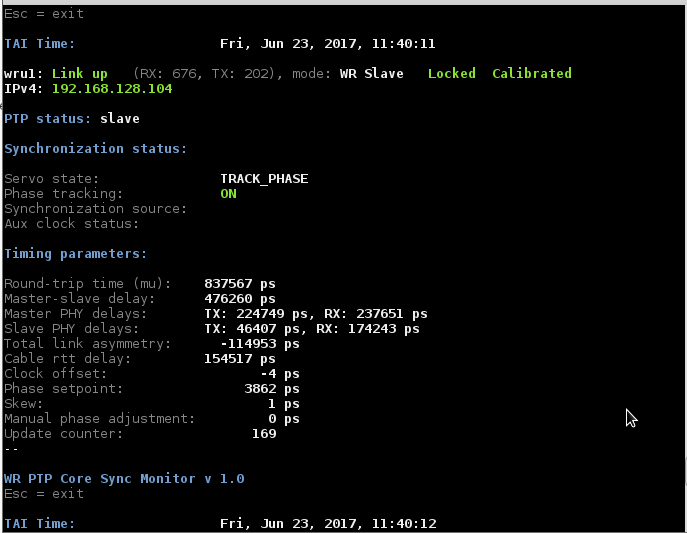
- Confirm that 'gui' shows TRACK_PHASE, Sync starts with SYNC_NSEC-> SYNC_PHASE->TRACK_PHASE
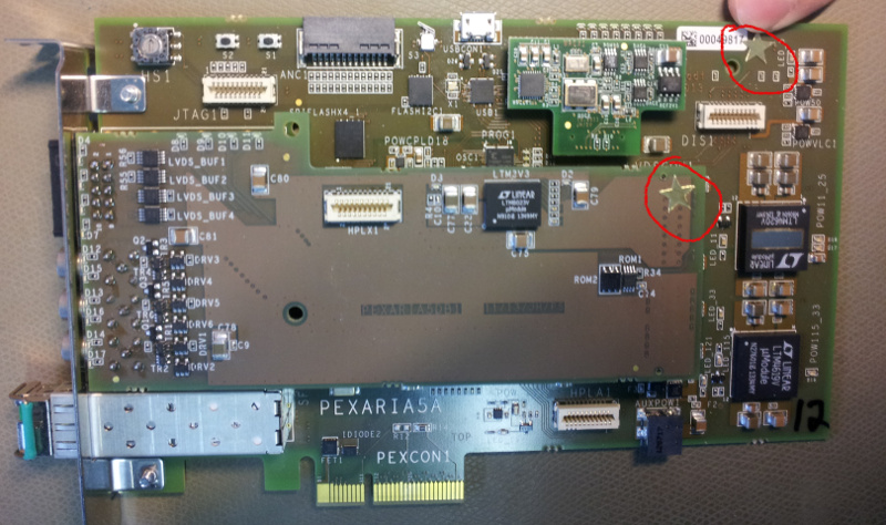
- Apply gold star to addon- and base-board


| I | Attachment | Action | Size | Date | Who | Comment |
|---|---|---|---|---|---|---|
| |
0bda56620605e2d534e9e88b508143fe.jpeg | manage | 71 K | 2017-06-26 - 13:27 | UnknownUser | Auto-attached by ImagePlugin |
| |
26_29_31_35quartus_prog.png | manage | 98 K | 2017-06-26 - 13:43 | UnknownUser | Quartus programming screenshot |
| |
30_flashprg-2_2.png | manage | 61 K | 2017-06-26 - 13:47 | UnknownUser | |
| |
30_flashprg_1_2.png | manage | 59 K | 2017-06-26 - 13:46 | UnknownUser | Flasherase_1_2 |
| |
32_ebconfig_detvttyusb0.png | manage | 12 K | 2017-06-26 - 13:57 | UnknownUser | eb-config-nv |
| |
33_eb-w1-write.png | manage | 12 K | 2017-06-26 - 14:01 | UnknownUser | Format eeprom |
| |
36_eb_flash.png | manage | 15 K | 2017-06-26 - 14:03 | UnknownUser | eb_flash pci_control.rpd |
| |
37_setmac.png | manage | 130 K | 2017-06-26 - 14:05 | UnknownUser | ebconsole run |
| |
42_eb_console.png | manage | 46 K | 2017-06-26 - 14:07 | UnknownUser | |
| |
43_44_ipaddress_cklockphasecheck.png | manage | 41 K | 2017-06-26 - 14:23 | UnknownUser | ipandclkoffset |
| |
46_io-testcall_ohne_anschluesse.png | manage | 14 K | 2017-06-26 - 14:27 | UnknownUser | |
| |
4d33c596293499727c0825f0b7e739d5.jpeg | manage | 60 K | 2017-06-26 - 13:27 | UnknownUser | Auto-attached by ImagePlugin |
| |
PexariaTestprotokoll.ods | manage | 1 MB | 2017-09-19 - 13:46 | UnknownUser | Vorlage Testprotokoll |
| |
PexariaTestprotokoll.pdf | manage | 1 MB | 2017-09-19 - 13:44 | UnknownUser | Beispiel Testprotokoll |
| |
fa1ea502a812c418ff6616de44b6bf02.jpeg | manage | 36 K | 2017-09-19 - 13:20 | UnknownUser | Auto-attached by ImagePlugin |
| |
flash-fx2lp-E.png | manage | 22 K | 2017-06-26 - 13:50 | UnknownUser | Screenshot Erase FLASH |
| |
lm32-mil-event-jitter.png | manage | 46 K | 2017-06-26 - 17:07 | UnknownUser | |
| |
pex-in-pc.jpg | manage | 212 K | 2014-06-27 - 13:09 | UnknownUser | |
| |
pex-s3.jpg | manage | 200 K | 2014-06-27 - 13:08 | UnknownUser | |
| |
pex-scope.jpg | manage | 238 K | 2014-06-27 - 13:09 | UnknownUser | |
| |
pex-setup.jpg | manage | 205 K | 2014-06-27 - 13:08 | UnknownUser | |
| |
pex-star.jpg | manage | 173 K | 2014-06-27 - 13:09 | UnknownUser | |
| |
pex-test.jpg | manage | 119 K | 2014-06-27 - 13:12 | UnknownUser | |
| |
promo14.jpg | manage | 115 K | 2014-06-27 - 13:08 | UnknownUser | |
| |
promo28.jpg | manage | 131 K | 2014-06-27 - 13:08 | UnknownUser | |
| |
wbm0mitgui_ipundtimingtest.png | manage | 38 K | 2017-06-26 - 14:28 | UnknownUser |
Please login to edit this topic
Topic revision: r20 - 2017-12-05, dbeck
Ideas, requests, problems regarding GSI Wiki? Send feedback | Legal notice | Privacy Policy (german)