You are here: GSI Wiki>TOS/Timing Web>TimingSystemOverview>TimingSystemContext (2024-12-16, DietrichBeck)Edit Attach
The Timing System and its Context in the Accelerator Control System
What is described here has been compiled from the Common Specifications for the Accelerator Control System (PSP 2.14.10) and updated in early 2018. Table of ContentsControl System Architecture
The control system of the the accelerator can be categorized in three levels - application layer, middle tier and equipment layer.Context of the Timing System
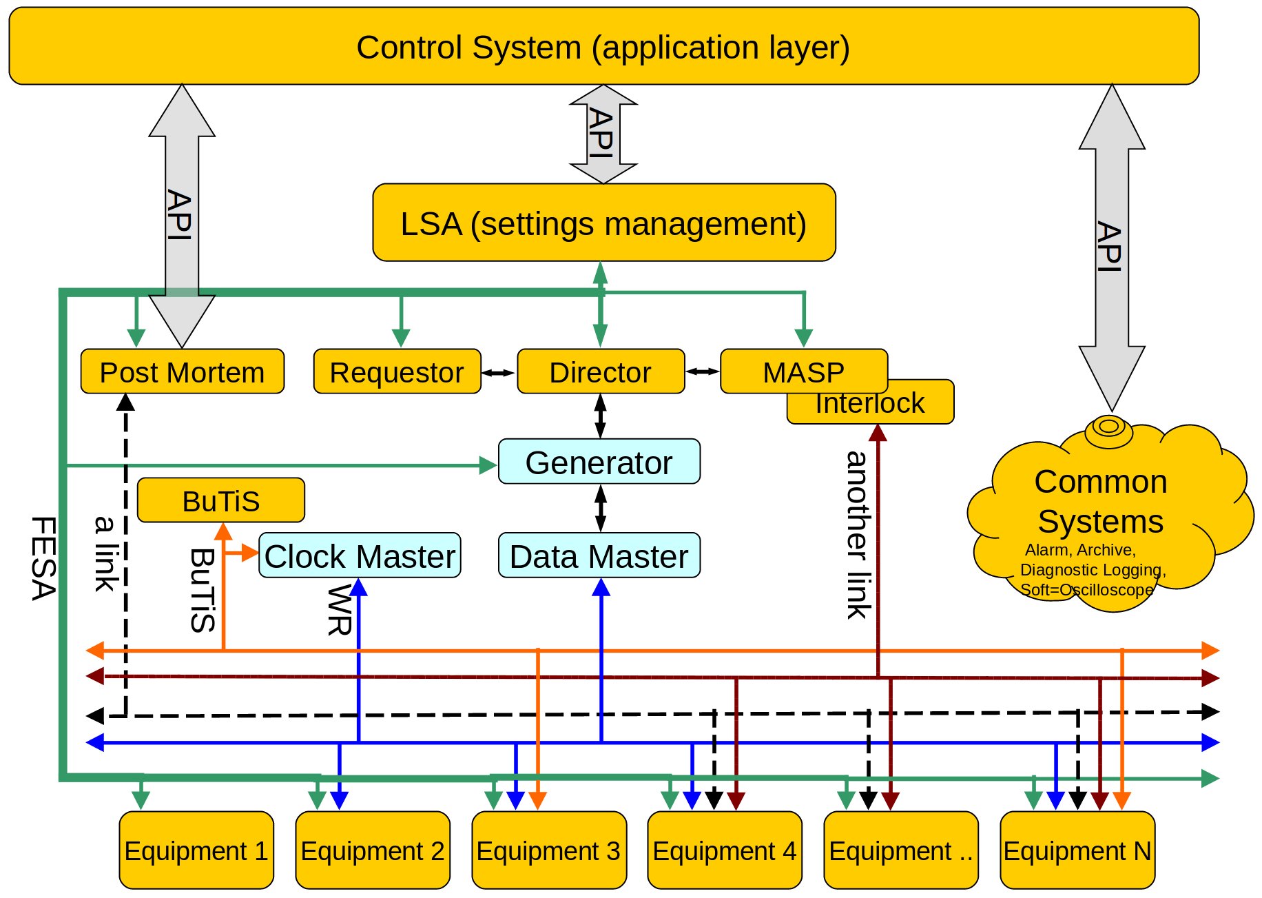
The figure below, depicts the functional relationship between the General Machine Timing (GMT) system and other components of the accelerator control system. Figure: The GMT and other components of the control system. The GMT components shown are Clock Master, Data Master and Generator (blue boxes) as well as the White Rabbit network (WR, blue arrows). Other components of the control system are shown in orange boxes or non-blue arrows.
The Data Master controls the GSI and FAIR facilities in hard real time, by broadcasting so-called timing messages via the White Rabbit network. The Data Master has no interfaces towards the higher layers except the Generator, that generates instructions for the Data Master based on input from upper control system layers. Relevant for the GMT are
 - Settings Management LSA. It provides set-values to all components, including the FESA based front-end computers. The set-values for the Generator include so-called patterns that are sent to the Generator.
- Requestor. Users or operators request configured beams from the requestor. This can be done via a software interface or via the 'Scheduling App' in the control room. A request is sent to the Director.
- MASP. It concentrates alarm and relevant status information. If a configured beam must not be played due to interlocks, alarms or bad status, it instructs the Director not to play the beam.
- Director. Depending on the data received from the "Requestor" and "MASP", it decides which beam are to played or not and instructs the Generator accordingly.
- The figure above is drawn from the point of view of the timing system.
- Arrows indicate relationships or (sub-)systems and not network links or field-buses.
- Some systems are not only situated on a single computer but distributed over the whole campus.
- Productions chains typically involve more than one accelerator which is not shown in the figure.
LSA and FESA
Typically, a configuration of a beam production chain is initiated from the application layer via an API of the settings management LSA. The production of the beam itself is like the performance of a piece of music. The composition is arranged by a composer LSA, the Controls Middleware (CMW) takes care of distributing the sheets of music to the musicians FECs (Front-End Computers). The conductor (here: timing system), conducts the musicians (resembled by FESA classes on the FECs connected to the equipment) and keeps them synchronized. As an example, if a power supply has the task of ramping a magnet, LSA calculates the shape of the ramp and its timing. The CMW distributes the parameters to the equipment ( what to do) and to the timing system ( when to do). During production of the beam, the timing system triggers the required action by generating timing events at the FECs. Typical equipment has two Ethernet connectors. The first connects to the accelerator network for receiving Set-Values (and other) data. The second is connected to the White Rabbit network. Please note, that the Timing Master is a FESA device.BuTiS
For some equipment, the precision achieved by the timing system is not sufficient. Then, the timing system is complemented by BuTiS. While the timing system distributes timing events and TAI time stamps, BuTiS provides distributed, high-precision clock signals (sine and pulse) over the whole campus. The Timing Master and the BuTiS center (not shown) must be linked such, that the BuTiS clock and TAI time stamps are synchronized. At the equipment side, dedicated BuTiS receivers are required (not shown).Beam Interlock System
The purpose of the beam interlock system is only to prevent further beam production in case of a malfunction with a latency of up to 100ms. The output data of the beam interlock system flow via MASP -> Director -> Generator to the Data Master. The latency till the information reaches the Data Master may be in the order of one second. It is not the task of the beam interlock system or the timing system to protect the machine or equipment. Features like 'beam abort' or dumping the beam are not within the scope of the GMT and must be implemented elsewhere. -- DietrichBeck - 28 Jan 2019| I | Attachment | Action | Size | Date | Who | Comment |
|---|---|---|---|---|---|---|
| |
timingSystem_context.jpg | manage | 292 K | 2018-02-19 - 09:48 | UnknownUser |
Edit | Attach | Print version | History: r20 < r19 < r18 < r17 | Backlinks | View wiki text | Edit wiki text | More topic actions
Topic revision: r20 - 2024-12-16, DietrichBeck
 Copyright © by the contributing authors. All material on this collaboration platform is the property of the contributing authors.
 Ideas, requests, problems regarding GSI Wiki? Send feedback | Legal notice | Privacy Policy (german)


