You are here: GSI Wiki>STF Web>CurrentMeasurementEquipment>GeraeteDokummentation>PowerConverterDocumentation>PowerConverterTriggerLines (2017-05-17, AlexanderWarth)Edit Attach
Using the general input output of the SCU for TTL triggers
2025-05-09Introduction
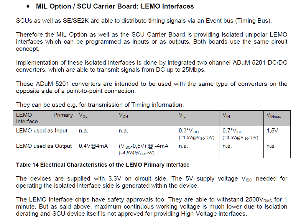
The SCU provides 2 groups of lemo inputs. At the stage of this writing only two of them are available- line 1
- line 2
-
TOP:PC:TRIGGER_LINES:FLAG_CYCLE -
TOP:PC:TRIGGER_LINES:FLAG_RAMP -
TOP:PC:TRIGGER_LINES:TRIGGER_CYCLE -
TOP:PC:TRIGGER_LINES:CYCLE_ALLOW_LINE
Enabling/Disabling the line
The different GIO can be assigned to the different functionality. One line can only be assigned to one functionality.- The functionality is disabled by setting the variable to 0
- It is enabled by setting the variable to the line number to be used
TOP:PC:TRIGGER_LINES:CONFIGUREmust be executed by assinging some long value to it (e.g 0). This will then make the power converter evaluate the differnet variables and then make the required configuration. Please note the power converter program is picky that only one line is assigned to one of the input or output variables. If one line is assigned to more than one of the variables it will not give any proper information on the offening variable.
Inputs
Enabling the next cycle
The power converter can run continuous cycles. Before each cycle is executed it can check a specified line, if it is active (TTL high). If so it will execute a single cycle. The line is specified using the variableTOP:PC:TRIGGER_LINES:CYCLE_ALLOW_LINE
Triggering the start of the next cycle
This functionality is quite similar to the functionality above. But in this mode the power converter will wait until the line goes to TTL Low. Please be aware it is "level triggered". This means the program proceeds the following way:- It will check if the line specified by
TOP:PC:TRIGGER_LINES:TRIGGER_CYCLEis TTL low - If not it will poll this line periodically until it is TTL low up to a maximum time specified by
TOP:PC:TRIGGER_LINES:TIMEOUT. This value can be set up to 65 seconds. It's default is 1 second. - During this polling no further line is checked!
Outputs
Flagging the cycle
When a line is assigned toTOP:PC:TRIGGER_LINES:FLAG_CYCLEis set, the program will set this line to
- TTL low before the first pause of the cycle
- to TTL high before it executes the first ramp (change of current) of the cycle
Flagging the ramp
When a line is assigned toTOP:PC:TRIGGER_LINES:FLAG_RAMPthe power converter will indicate when it is executing a ramp. Thus it will set the line
- to TTL high when it executes the ramp (change of current)
- to TTL low when it finished the ramp
- read back the set value of the function generators
- read back the value of the ADC's
- check that these are appropriate
- calculate the parameters for the next ramp
Adding new trigger lines
- add an appropriate variable to the
struct power_converter_ramp_tinpower_converter_ramp_loop.h - implement appropriate get/set "methods" best in
power_converter_ramp.c - add these to
array trigger_nodesinpc_server_parser_tree.c - add the handling in
power_converter_trigger_lines_scu.icin functionpower_converter_trigger_setup - recompile all files in the folder pc by executing
-
- make clean
- make
- test it!
- send me a post card if the description works exactly as given here
- SCU_LEMO_Interfaces:

| I | Attachment | Action | Size | Date | Who | Comment |
|---|---|---|---|---|---|---|
| |
SCU_LEMO_Interfaces.png | manage | 81 K | 2016-12-02 - 16:13 | RobertJaeger | SCU_LEMO_Interfaces |
Edit | Attach | Print version | History: r4 < r3 < r2 < r1 | Backlinks | View wiki text | Edit wiki text | More topic actions
Topic revision: r4 - 2017-05-17, AlexanderWarth
 Copyright © by the contributing authors. All material on this collaboration platform is the property of the contributing authors.
 Ideas, requests, problems regarding GSI Wiki? Send feedback | Legal notice | Privacy Policy (german)


