|
|
You are here: GSI Wiki>FRS Web>S2GasTarget (2021-07-10, SagarRoy)
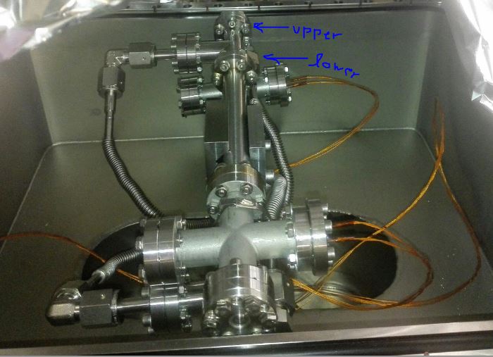
S2 — Gas Target (GTS3ET7GS)
FRS Home Page -Two tubes with thin windows connected to a flange for gas inlet and outlet.
The pressure is measured before inlet and behind outlet, thermo sensors are installed directly on the target.
Positions:
upper tube in beam, y = -81.8 mm -> -83.5 mm (new April 2020)
lower tube in beam , y = -43.0 mm -> -42.5 mm (new April 2020)
upper end switch y = -41.4 mm
lower end switch y = -603.2 mm
Caution: The gas target coming from below could crash with the degrader drives coming from above.
However, the degrader drives are limited by end switches to avoid this. In addition,
an interlock prohibits motion of degraders when the gas target is not at lower end switch,
and vice versa the gas target drive is blocked when not all three degraders are at their upper end position.
 Updated Feb 19, 2020
-- SagarRoy - 2021-06-26
Updated Feb 19, 2020
-- SagarRoy - 2021-06-26 

Topic revision: r2 - 2021-07-10, SagarRoy
Ideas, requests, problems regarding GSI Wiki? Send feedback | Legal notice | Privacy Policy (german)