You are here: GSI Wiki>Epics Web>EpicsProjectsAndActivities>ApplicationsGSI>HadesRpcGasSystemMonitor (2015-07-31, PeterZumbruch)Edit Attach

HADES RPC Gas System Monitor
- Introduction
- Hardware setup
- Software
- Operation
- Tarball (snapshot as of 25 May 2011)
- FAQ
- Outlook / Requests
- Contact
Introduction
Besides the Threshold setting and Temperature/Voltage/Current Monitoring the RPC (resistive plate chamber) detector of HADES requires EPICS based monitoring of their gas system parameters.The data of the gas system are retrieved by a proprietary hardware controller controlling/monitoring flow (set/get), and (differential) pressure (get). It is accessible via CANbus. This CANbus is connected to a HADcon(trol) general purpose board, where an EPICS Server is running. This IOC collects the data provided by the HADcon's microcontroller via the streamDevice protocol and provides them to EPICS clients such as a CSS based BOY GUI build for this purpose.

Hardware setup
Gas System
Parameters
- Gas flow [ccm/min]
- Flow Controllers:
- C4H10 (set/get)
- R134a (set/get)
- SF6 (set/get)
- Flow meter
- sum flow cave in (get)
- sum flow cave out (get)
- Flow Controllers:
- Pressure (differential) [mbar]
- cave in
- cave out
- Temperature [°C]
- position/device unknown
- Physical alarm
- Read
- Reset
Controls/Monitoring Interfaces
| Fieldbus | Devices |
|---|---|
| CANbus | Gas System Monitor |
| 1-wire | Temperature Sensors |
Gas System Monitor
The gas system monitor amplifies the input voltages from the meters and controls - (types: unknown) - and digitizes the values of flow and pressures with two 8 channel 12 bit ADC. The ADCs (MCP3208) have an SPI Interface to communicate with. They communicate with a CANbus device accessible from the EPICS IOC via the HadCon's API and EPICS's StreamDevice. module.- Schematics of gas monitor's amplifier and ADC

- Schematics and layout of the Gas System Monitors's CANbus Controller

- Schematics of connector board

CANbus settings
- Speed: 250kBits/s
- Termination: Internally there is already a 120Ω Resistor, which can be disabled by a jumper on the CANbus Controller
CANbus operations
Using the nomenclature of the HADcon's protocol the CANbus commands to talk with Gas system are: (numbers are hexadecimal !)read out the Flow Controller settings
- CANbus ID:
101 - command:
SEND 101 1 1 8 - response:
RECV<xx>101 8<X1> <X2> <X3> <X4> <X5> <X6> <X7> <X8>
<X1> MSByte Flow Controller 1 <X2> LSByte Flow Controller 1 <X3> MSByte Flow Controller 2 <X4> LSByte Flow Controller 2 <X5> MSByte Flow Controller 3 <X6> LSByte Flow Controller 3 <X7>, <X8> not used <xx> internal, arbitrary number, to be ignoredvalue [integer] = MSByte << 8 + LSByte
read out the Flow Controller value readings
- CANbus ID:
102 - command:
SEND 102 1 1 8 - response:
RECV<xx>102 8<X1> <X2> <X3> <X4> <X5> <X6> <X7> <X8>
<X1> MSByte Flow Controller 1 <X2> LSByte Flow Controller 1 <X3> MSByte Flow Controller 2 <X4> LSByte Flow Controller 2 <X5> MSByte Flow Controller 3 <X6> LSByte Flow Controller 3 <X7> status of physical alarm (0x0: ok, 0x1: error) <X8> not used <xx> internal, arbitrary number, to be ignoredvalue [integer] = MSByte << 8 + LSByte
read out the Flow Meter value readings
- CANbus ID:
201 - command:
SEND 201 1 1 8 - response:
RECV<xx>201 8<X1> <X2> <X3> <X4> <X5> <X6> <X7> <X8>
<X1> MSByte Flow Meter 1 <X2> LSByte Flow Meter 1 <X3> MSByte Flow Meter 2 <X4> LSByte Flow Meter 2 <X5>, <X6>, lt;X7>, <X8> not used <xx> : internal, arbitrary number, to be ignoredvalue [integer] = MSByte << 8 + LSByte
read out the Pressure sensor value readings
- CANbus ID:
301 - command:
SEND 301 1 1 8 - response:
RECV<xx>301 8<X1> <X2> <X3> <X4> <X5> <X6> <X7> <X8>
<X1> MSByte Pressure Sensor 1 <X2> LSByte Pressure Sensor 1 <X3> MSByte Pressure Sensor 2 <X4> LSByte Pressure Sensor 2 <X5>, <X6>, lt;X7>, <X8> not used <xx> : internal, arbitrary number, to be ignoredvalue [integer] = MSByte << 8 + LSByte
delete a physical alarm on the gas controller (TODO)
- CANbus ID:
400 - command:
SEND 400 1 1 8 - response:
RECV<xx>400 8<X1> <X2> <X3> <X4> <X5> <X6> <X7> <X8>
<X1>, <X2>, lt;X3>, <X4> <X5>, <X6>, lt;X7>, <X8> not used <xx> : internal, arbitrary number, to be ignored
Calibration parameters (Alberto Blanco, Orlando Cunha)
| device | Description | set/get | equivalents | formula | slope | offset |
|---|---|---|---|---|---|---|
| ADC | 0 ⇔ 0 Volt | U [V] = <Slope>× ADC [] + <Offset> |
0.002 V | 0 V | ||
| 4000 ⇔ 8 Volt | ||||||
| |
||||||
| Flow Controller 1 | Freon - R134a | set | 5V ⇔ 200 cc/min | Flow [cc/min] = <Slope>× U [V] + <Offset> |
40 (cc/min)/V | 0 cc/min |
| |
|
|||||
| output | 5V ⇔ 200 cc/min | 40 (cc/min)/V | 0 cc/min | |||
| |
|
|||||
| Flow Controller 2 | SF6 Hexafluoride | set | 5V ⇔ 20 cc/min | 4 (cc/min)/V | 0 cc/min | |
| |
|
|||||
| output | 5V ⇔ 20 cc/min | 4 (cc/min)/V | 0 cc/min | |||
| |
|
|||||
| Flow Controller 3 | C4H10 Isobutane | set | 5V ⇔ 20 cc/min | 4 (cc/min)/V | 0 cc/min | |
| |
|
|||||
| output | 5V ⇔ 20 cc/min | 4 (cc/min)/V | 0 cc/min | |||
| |
|
|||||
| Flow Meter 1 | input cave | output | 5V ⇔ 1000 cc/min | 200 (cc/min)/V | 0 cc/min | |
| |
|
|||||
| Flow Meter 2 | output cave | output | 5V ⇔ 1000 cc/min | 200 (cc/min)/V | 0 cc/min | |
| |
||||||
| Pressure Sensor 1 | input cave | output | 0.5V ⇔ 0 mbar | p [mbar] = <Slope>× U [V] + <Offset> |
17.5 mbar/V | -9.485 mbar |
| 4.5V ⇔ 70 mbar | ||||||
| |
|
|||||
| Pressure Sensor 2 | output cave | output | 0.5V ⇔ 0 mbar | 17.5 mbar/V | -8.015 mbar | |
| 4.5V ⇔ 70 mbar | ||||||
| |
||||||
HADCon (installation details, firmware, etc, → Sergey Yurevich (HADES))
- The technical details for this device can be found at:
- Details to the API and its generalization used for the communication between ETRAX and micro controller
- Name of the device
- etrax208 / etraxp208
- Prerequisites
- NFS
- it is not mandatory, but the coding expects an NFS mounted device mounted on
/home/hadaq/having a sub directoryEPICS/epics_apps.
- it is not mandatory, but the coding expects an NFS mounted device mounted on
- Firewall open for EPICS ports 5064/5065
- For automation: environment variable HOSTNAME should be set to etrax208 at boottime
- ntp server / correct time
- procServ should be installed locally on etrax208 to provide automatic restart ( binary is included in the following code)
-
/home/hadaq/rc, executed automatically at boot time should contain a sequence callingwhich needs the subdirectory# --------------------------- # start EPICS IOC script # - checks in script $startEpicsIocScript # for matching hostnames and starts IOC in background # P.Zumbruch, GSI, 11-02-2010
startEpicsIocScript=/home/hadaq/EPICS/startupProcedures/startEpicsIoc.sh startEpicsIocListFile=/home/hadaq/EPICS/startupProcedures/iocListFile-Etrax.txt startEpicsIocCommand="$startEpicsIocScript -f $startEpicsIocListFile" [ -x "$startEpicsIocScript" ] && [ -f "$startEpicsIocListFile" ] && $startEpicsIocCommand || echo "$startEpicsIocScript" failed unset startEpicsIocScript startEpicsIocListFileEPICS/startProcedures, which is available via CVS:- Repository
:ext:hadaq@lxi001.gsi.de:/misc/hadesprojects/daq/cvsroot - Module:
EPICS/startupProcedures/hadcon/EPICS/startupProcedures
- Repository
-
- NFS
Software
The EPICS IOC executables, databases, startup, and protocol files presented here are part of the overall file sets used for the HADES setup. Only those relevant for this project are described/mentioned. It can be reduced to this purpose and be run standalone.EPICS
- Base: 3.14.10
- Asyn: 4.9
- StreamDevice: 2.4 including patches
CVS Repository
- Repository
:ext:hadaq@lxi001.gsi.de:/misc/hadesprojects/daq/cvsroot - Module:
hadcon/epics_apps/streamHadcon
IOC Server
The server's structure is this of a typical EPICS application IOC:-
streamHadconApp, application directory with its sub directories: *src, no special coding here, but includingstreamDevice.dbdandasyn.dbd*Db, contains the database elements *protocols, contains the streamDevice protocols -
bin,db,dbd,lib, directories build during compile time -
configure, changeRELEASEfile appropriate to yourEPICS_BASEsettings -
iocBootand its sub directory, contains the startup command file and environment settings
$> ../../bin/linux-cris_v10/streamHadcon st.cmdstartup file
-
st.cmd- master command file,
- defining among other things
asynparameters for a port calledhadcon, a serial device connecting to the micro controller - defines the path to the protocol files
- includes hostname specific startup file based on the environment variable
HOSTNAME, which should be/have been set at startup of the hadcon, or by hand.
-
st_etrax208- hostname specific startup file (
HOSTNAME = etrax208) - loads the databases specific needed for this host's tasks ( flow and pressure readout via CANbus and temperature readout via 1-wire ) details see: section database
-
hadcon_global.db,hadcon_debug_global.db: auxillary records -
hadcon_oneWire_temperature_ID_etrax208.db: database for the 1-wire temperature readout -
hadcon_can_rpc_gas_system_etrax208.db: database for the flow and pressure readout AND for the overall readout/access sequence connecting to porthadcon
-
- hostname specific startup file (
protocol functions
To access and readout the micro controller via the asyn porthadcon the following streamDevice protocol functions have been implemented (details, like delimiter q.v.
.proto files): - CANbus functionality (flow and pressure data):
hadcon_CAN.proto-
get8_CAN(canID,busMask,RTR_bit,no.bytes,prefix), values are hexadecimal- Example of command:
field(INP, "@hadcon_CAN.proto get8_CAN(201,1,1,8,etrax208:Pressure)- sends out the following:
SEND 201 1 1 8 - waits for immediate/synchronous (RTR=1) answer:
RECV xx 201 8<b1> <b2> <b3> <b4> <b5> <b6> <b7> <b8> - fills each data byte
<b1 ... b8>to a single record called<prefix>_1 ... 8 - if answer differs streamDevice increases the severity and fills the records
<prefix>:errorand<prefix>:errorNr
- sends out the following:
- Example of command:
-
- 1-wire temperature readout:
hadcon_OWTP_intr.proto- runs by asynchronous send and receive, since temperature and internal calibration readout takes too long ( ~1 second )
- sending
OWTP- Example of command:
field(INP, "@hadcon_OWTP_intr.proto OWTP hadcon")- just sends out the following: and triggers the readout and calibration of all connected 1-wire temperature sensors
OWTP
- just sends out the following:
- Example of command:
- receiving
OWTP_read_ID_intr(ID)- Example of command:
field(INP, "@hadcon_OWTP_intr.proto OWTP_read_ID(10D753E3000800D6) hadcon")- waits via I/O intr mechanism for this matching message: and fills
RECV OWTP 10D753E3000800D6<value><value>to its record.
- waits via I/O intr mechanism for this matching message:
- Example of command:
database
Besides the pure access and retrieval of the data via streamDevice protocol functions, other aspects had to be considered:- modularity and reusability
- sequential access to the data bottle neck serial port of the HADCon
- the micro controller code has (up-to-know: 24 Feb 2011) no internal buffering of messages, neither in nor out
-
hadcon_can_rpc_gas_system_etrax208.substitutionsuses those template files-
hadcon_global_scan_rpc_gas_system.template -
hadcon_can_get8byte_rtr.template -
hadcon_can_rpc_gas_system_call_calc.template -
hadcon_can_rpc_gas_system_join_and_calibrate.template- here the calibration parameters can be changed
-
hadcon_can_rpc_gas_system_set_physical_alarm_status.template -
hadcon_can_rpc_gas_system_physical_alarm_status.template
-
-
hadcon_oneWire_temperature_ID_etrax208.substitutions-
hadcon_oneWire_temperature_ID_DS18B20.template -
hadcon_oneWire_temperature_ID_DS18S20.template
-
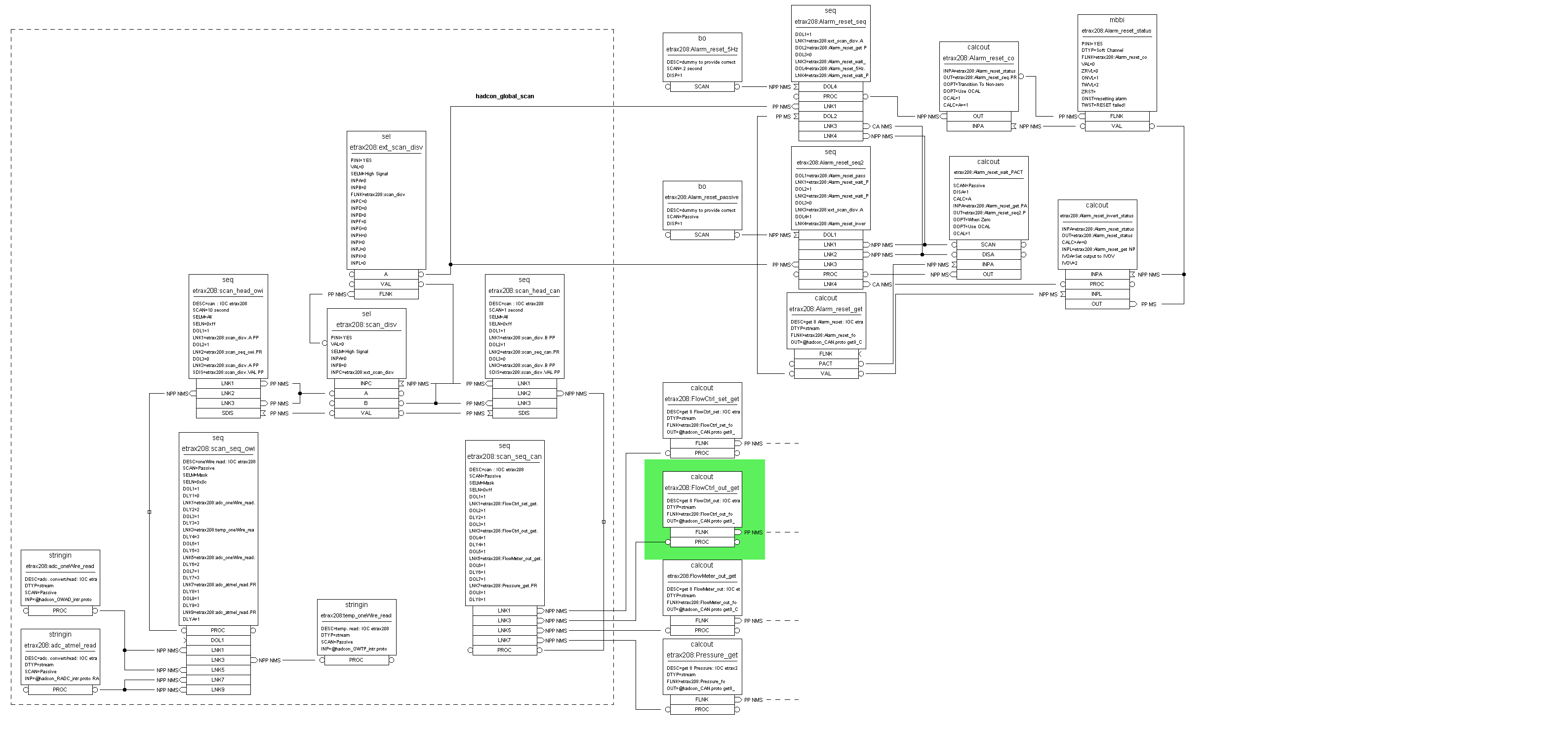
hadcon_global_scan_rpc_gas_system.template - Only two complementary sequence records trigger the readout
- one for the 1-wire access and one for the CANBus
- while one is active the other one is disabled
- Those two sequences call themself the actual readout sequence records, which trigger the streamDev records, and the data handling
- master loop calling the sequential readout
 shows this concept

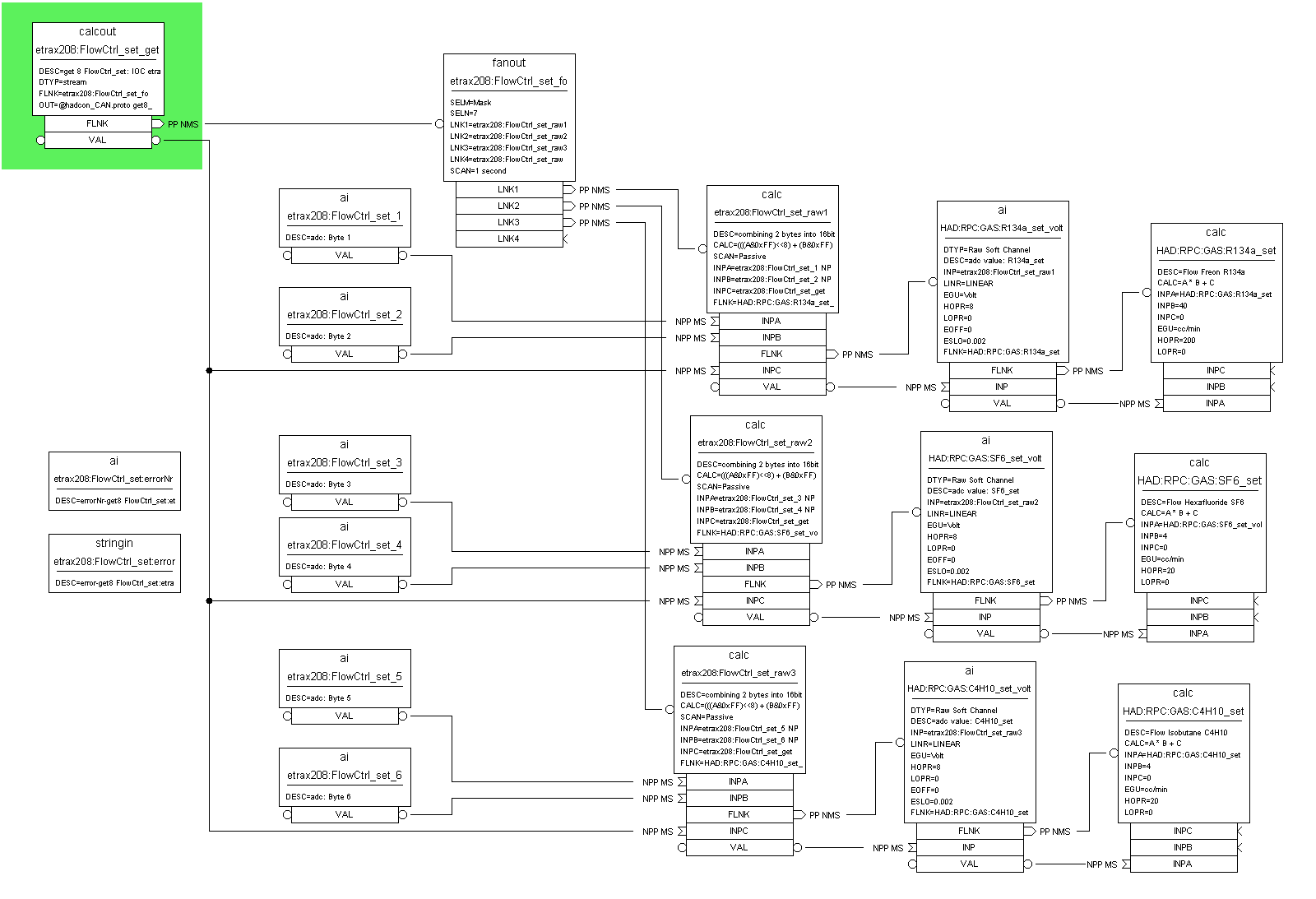
- while the following item describes the pressure readout chain as exemplary showcase
 :
:

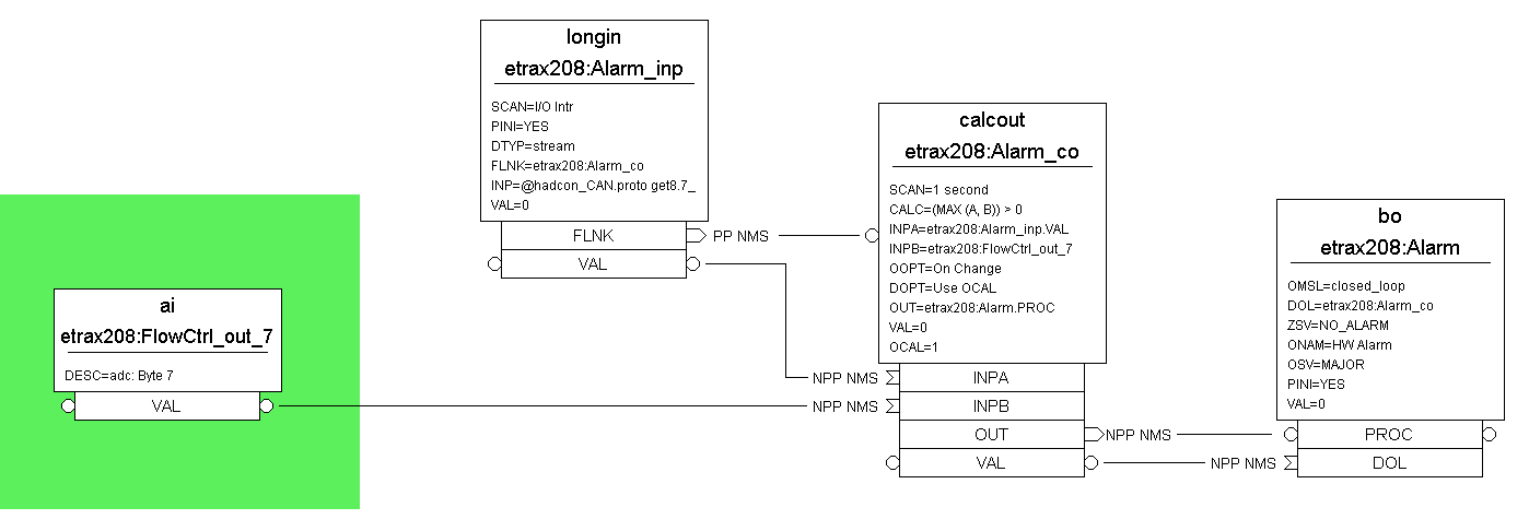
- The alarm status of the hardware is retrieved via
- an unused byte of the Flow Controller value readings alarm
- and by an additional high priority CANbus message:
- hardware alarm status handling
 shows this concept

- master loop calling the sequential readout
- In addition a third write access sequence has been added which blocks the other sequences, which is up-to-now used for:
- resetting the physical alarm
CSS Client
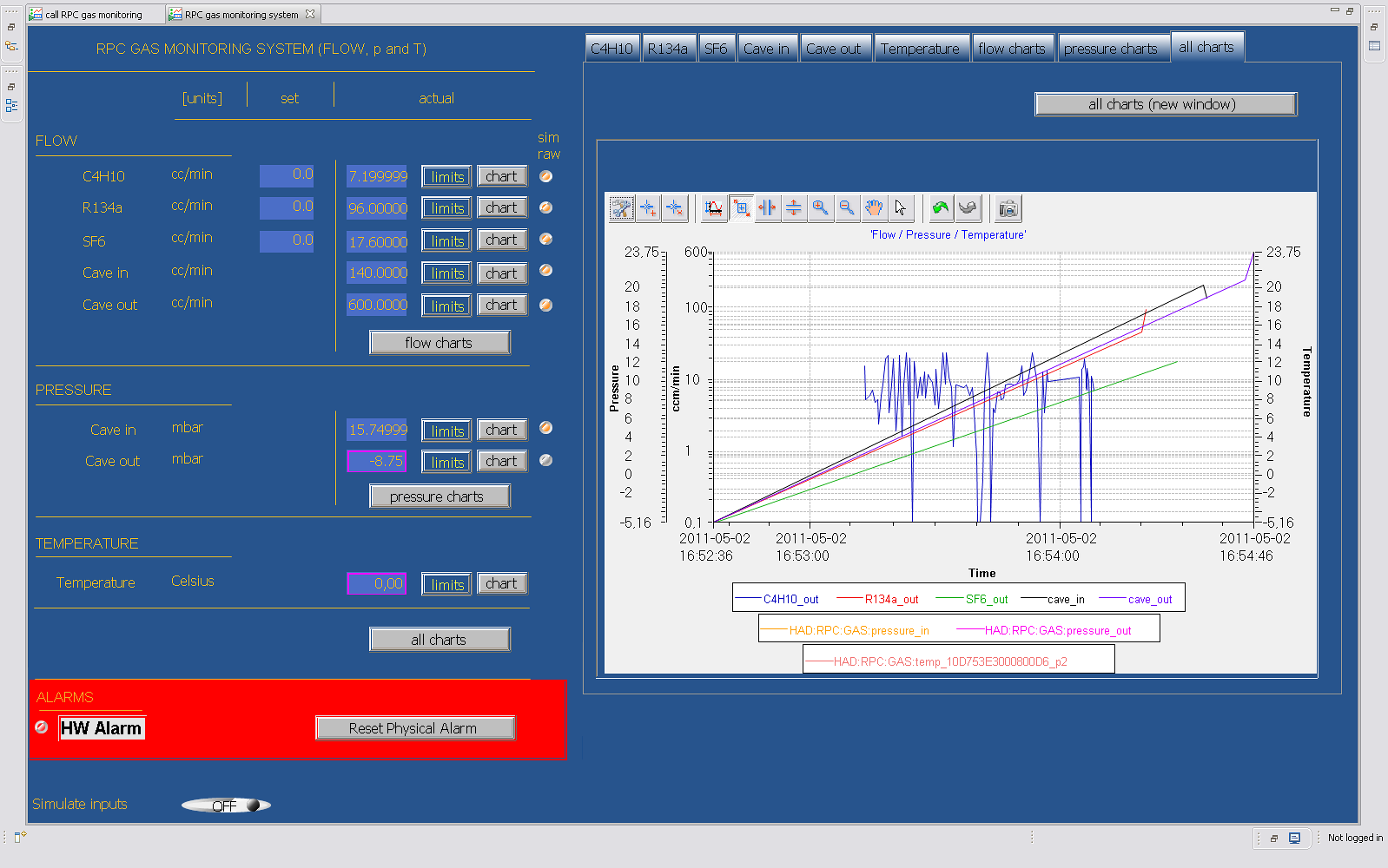
- BOY GUI Based on the SNS flavor of the CSS (control system studio and its operator interface BOY this independent GUI has been created.
- Repository
:ext:hadaq@lxi001.gsi.de:/misc/hadesprojects/daq/cvsroot - CVS Module:
hadcon/epics_apps/streamHadcon/gui/boy/rpc_gas_system_flow_and_pressure - boy screenshot:

- Repository
Operation
Starting the server
automatic
Provided you have- supplied the
EPICS/startupProcedures, - and the
/home/hadaq/rcentries, - and your machine is
etrax208(or is listed in the startup Procedure config files), the IOC server should come up automatically - after reboot,
- (ab)normal ending of the EPICS IOC
by Hand
w/ procServ
IfprocServ is already running but epics not, then - already logged via telnet to the hadcon again login via telnet:
user@etrax208> telnet localhost 4813 - type
exitto exit a running IOC server- if this does not work kill the leading IOC process of the result of a
pscommand
- if this does not work kill the leading IOC process of the result of a
- use
CTRL+Rto restart the server, if automatic restart is toggled of byCTRL+T
- NOTE: you can exit a telnet session by typing
CTRL+]followed by the telnet commandquit
w/o procServ
- make sure, via
psneither an IOC is already running, norprocServis running - change to directory
/home/hadaq/EPICS/epics_apps/streamHadcon/iocBoot/iocstreamHadcon_linux-cris_v10$> cd /home/hadaq/EPICS/epics_apps/streamHadcon/iocBoot/iocstreamHadcon_linux-cris_v10 - if you want to make sure the environment variable
HOSTNAMEis set correctly export it$> export HOSTNAME=etrax208 - call from here the executable for your architecture with
st.cmdas argument$> ../../bin/linux-cris_v10/streamDevice st.cmd - the EPICS IOC should come up
- if you are hunting for an error, mind the messages and warnings during startup
Stopping the server
w/ procServ
- already logged via telnet to the hadcon again login via telnet:
user@etrax208> telnet localhost 4813 - toggle automatic restart by
CTRL+Tto the behavior you want to have (restart enabled/disabled) - type
exitto exit a running IOC server
- NOTE: you can exit a telnet session by typing
CTRL+]followed by the telnet commandquit
w/o procServ
- type
exitin the IOC shell of the server to exit a running IOC server
Starting the client
Provided you have CSS (SNS) installed on your client machine- type the corresponding startup command, e.g. "css"
client:$> css - make sure * to open the right workspace (if asked for), and * to have the corresponding project resource files available, e.g.
CSS-Workspaces/Default/rpc_gas_system_flow_and_pressure* you can retrieve it via CVS or via the attached tarball - In the Navigator Panel select the file
rpc_gas_system_flow_and_pressure_call.opi- double-click might already open this file in run-mode,
if not:- choose from the context menu (right mouse click) Open With>OPI Runtime , or
- if already opened, use the green circular run-button in the menu bar or
CTRL+G
- double-click might already open this file in run-mode,
Obstacles
- If you are sure your IOC server is running, but you just see disconnected messages,
- select from the menu bar Preferences ...
- choose the topic CSS Core>EPICS
- add your IOC server machine to the
addr_list - check
auto_addr_list
Tarball (snapshot as of 25 May 2011)
- IOC Server
- rpc_gas_system_monitor_IOC.7z: tarball IOC
- contains the necessary directory structure and files below the mount point
/home/hadaq - also contains the client resources
- CSS Client
- rpc_gas_system_monitor_GUI.7z: tarball GUI
FAQ
Outlook / Requests
Up to the user (RPC coimbra) or others.- 19.04.2011, Request, Alberto Blanco, Coimbra
- Hi,
The new CAN command to be implemented is"SEND 400 1 1 8". This deletes a physical alarm on the gas controller, therefore it is a command that writes from the HADCon to the Gas system.[...]- implemented, needs to be tested by RPC team -- PeterZumbruch - 12 May 2011
- 20.05.2011, Answer from Orlando Cunha, Coimbra , to implementation of a possible reading of the physical alarm, mentioned above
- The changes are made, the 7th byte of the read command of flow controlers (0x102) indicates the alarm status (byte = 0x00 if nothing happens, if there is alarm byte = 0x01). Does occur when an alarm condition will automatically send a command equal to the CAN Reading (0x102) with high priority (0xE0).
- implemented, needs to be tested by RPC team -- PeterZumbruch - 25 May 2011
- 21.07.2077, fine tuning request, Alberto Blanco, Coimbra
- [...]
- Flow Meter 1 is input cave and Flow Meter 2 is output cave. Luis decided to exchange the sensors when he installed it. Could you also invert them and change the documentation.
- changed - -- PeterZumbruch - 21 Jul 2011
- The offsets of Pressure Sensor 1 and Pressure Sensor 2 need a fine tunning (this fine tunning is sensor dependent. The current offset is taken from data sheet and probably is an average over many sensors). The exact offsets are: Pressure Sensor 1 = -9.485 and Pressure Sensor 2 = -8.015.
- changed - -- PeterZumbruch - 21 Jul 2011
Contact
→epics_at_gsi.de
-- PeterZumbruch - 31 Jul 2015
| I | Attachment | Action | Size | Date | Who | Comment |
|---|---|---|---|---|---|---|
| |
adc.pdf | manage | 29 K | 2011-02-25 - 09:38 | PeterZumbruch | schematic of gas monitor's amplifier and ADC |
| |
can-modulo.pdf | manage | 216 K | 2015-07-30 - 14:26 | PeterZumbruch | Schematics and layout of the Gas System Monitors's CANbus Controller |
| |
connector-board.pdf | manage | 477 K | 2015-07-31 - 09:42 | PeterZumbruch | Schematics of connector board |
| |
gui.png | manage | 121 K | 2011-05-26 - 11:49 | PeterZumbruch | boy gui |
| |
hadcon_can_rpc_gas_system_alarm.png | manage | 13 K | 2011-05-26 - 12:09 | PeterZumbruch | Alarm handling for physical alarm |
| |
hadcon_can_rpc_gas_system_caller.png | manage | 69 K | 2011-05-12 - 11:21 | PeterZumbruch | master loop calling the sequential readout |
| |
hadcon_can_rpc_gas_system_etrax208_principles.pdf | manage | 27 K | 2011-05-12 - 11:17 | PeterZumbruch | pressure readout chain as exemplary showcase |
| |
hadcon_can_rpc_gas_system_etrax208_principles.png | manage | 41 K | 2011-05-12 - 11:21 | PeterZumbruch | pressure readout chain as exemplary showcase |
| |
hadcon_can_rpc_gas_system_etrax208_principles_alarm.pdf | manage | 14 K | 2011-05-26 - 12:12 | PeterZumbruch | Alarm handling for physical alarm |
| |
hadcon_can_rpc_gas_system_etrax208_principles_call_and_alarms.pdf | manage | 27 K | 2011-05-12 - 11:14 | PeterZumbruch | master loop calling the sequential readout |
| |
rpc_gas_system.png | manage | 147 K | 2011-05-26 - 11:50 | PeterZumbruch | boy gui |
| |
rpc_gas_system_monitor_GUI.7z | manage | 20 K | 2011-05-25 - 11:30 | PeterZumbruch | tarball GUI |
| |
rpc_gas_system_monitor_IOC.7z | manage | 1 MB | 2011-05-25 - 11:23 | PeterZumbruch | tarball IOC |
Edit | Attach | Print version | History: r24 < r23 < r22 < r21 | Backlinks | View wiki text | Edit wiki text | More topic actions
Topic revision: r24 - 2015-07-31, PeterZumbruch
- User Reference
- BeginnersStartHere
- EditingShorthand
- Macros
- MacrosQuickReference
- FormattedSearch
- QuerySearch
- DocumentGraphics
- SkinBrowser
- InstalledPlugins
- Admin Maintenance
- Reference Manual
- AdminToolsCategory
- InterWikis
- ManagingWebs
- SiteTools
- DefaultPreferences
- WebPreferences
- Categories
 Copyright © by the contributing authors. All material on this collaboration platform is the property of the contributing authors.
 Ideas, requests, problems regarding GSI Wiki? Send feedback | Legal notice | Privacy Policy (german)


