You are here: GSI Wiki>TOS/Timing Web>TimingSystemDocumentation>TimingSystemDocuments>TimingSystemGroupsAndMachines (2025-04-04, DietrichBeck)Edit Attach
Groups and Machines
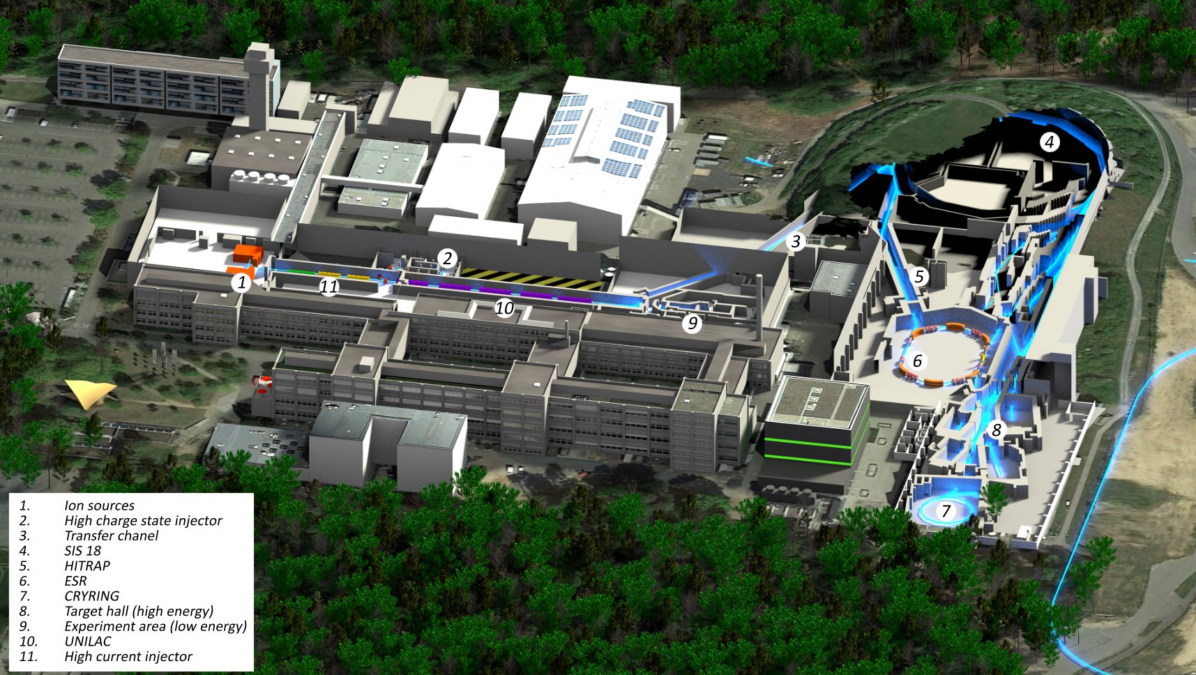 Figure: Overview on GSI accelerators. Click here for a larger image.
Overview
Accelerator equipment relevant for the control system is organized in groups. The Data Master of the timing system generates command messages for groups, but not for individual equipment. The equipment within a group belongs together conceptually. An example of a group might a ring machine. The ordering of equipment into groups is defined by the way the accelerator complex is operated. With the new timing system, the group ID is analogous to a machine ID. In principle, the ordering of equipment into groups depends on the role of the equipment for the production of a specific beam. There are two schools of thought. CCT (Controls Coordination)- A group is a collection of equipment that always belongs together.
- A specific equipment may only be member of one group.
- A specific equipment always belongs to the same group (that assignment to a group does not depend on a beam).
- Many groups (> 200) are required for the operation of the machine.
- What belongs together happens together.
- A specific equipment may be member of more than one group.
- When the operational concept of the machine is changed, new groups can be introduced and specific equipment can join another group too.
- The number of existing groups may be large
- The number of groups for the production of specific beams is small.
Group IDs
A group ID has 12 bit. This is divided into two ranges- 0d0000..0d1023 (0x000-0x3ff): operative, assignment by CCT
- 0d1024..0d4095 (0x400-0xfff): reserved, assignment by TOS
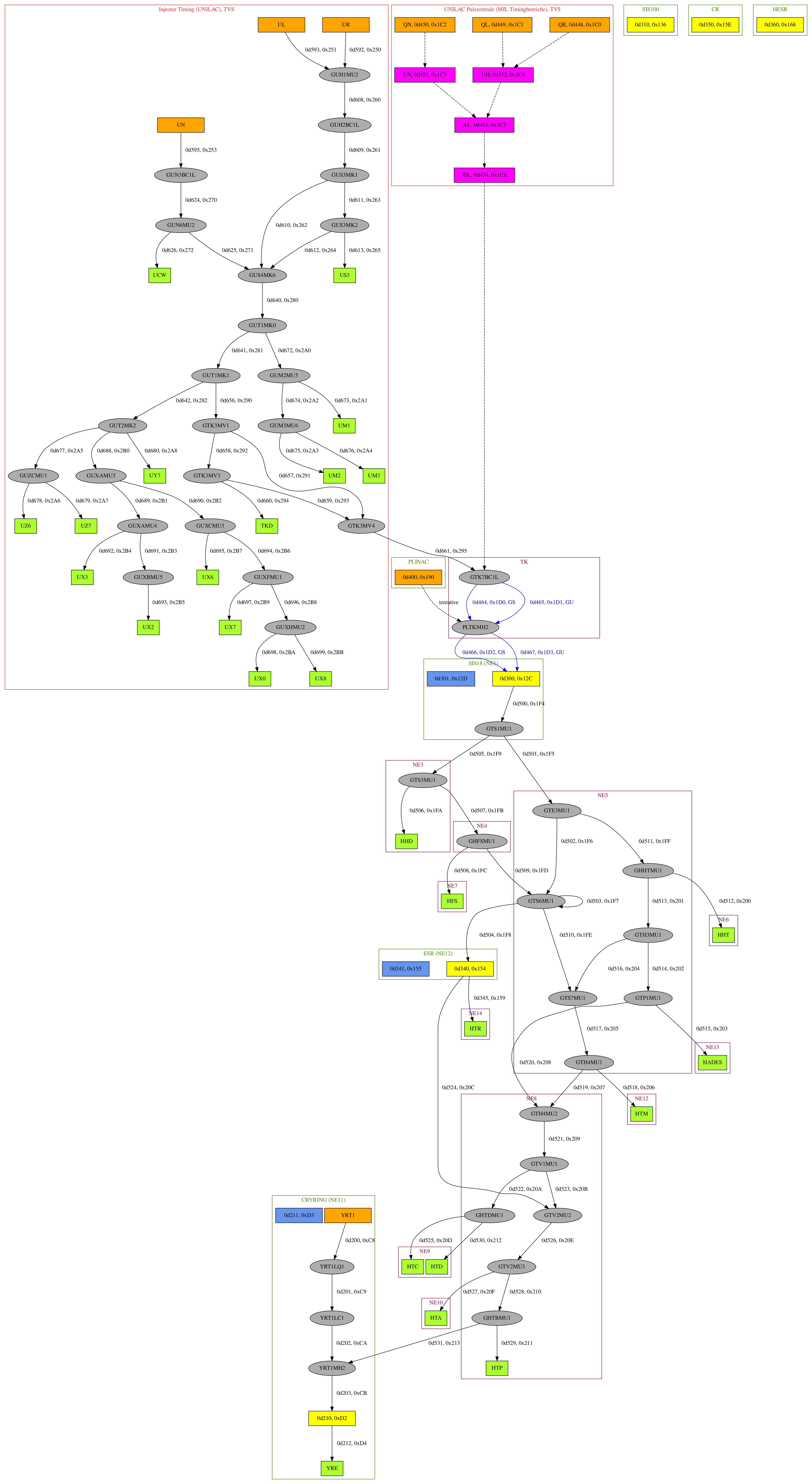 Fig 1: Timing Groups. Shown are rings (yellow), electron coolers (blue), ion sources (orange), UNILAC MIL-Timing sections (magenta), intersections (grey) and targets (green). A timing group (solid arrow) is named using the scheme
 origin_TO_destination, see table below. The group ID GID is given in decimal and hex on the right side of an arrow (rings, electron coolers: inside box). Dashed arrows are used to guide the eye and do not represent timing groups. Boxes with dark green or red (pink) borders denote accelerators or TVS (NE) areas, but the assignment of nodes to accelerators might not be correct for all cases. The red box indicated timing groups that must only be used within a distinct White Rabbit network dedicated to injectors. Since 2023 so called 'shared groups' exist, that are marked by blue colored arrows; here the accelerator is indicated next to the group number. Please note, that some adjacent GIDs are hex-aligned to allow for more efficient prefix matching.
Groups for Operation
| 0dGID | 0xGID | Name | Injector | Description |
|---|---|---|---|---|
| 200 | C8 | YRT1_TO_YRT1LQ1 | from ion source 1 to merging quadrupole | |
| 201 | C9 | YRT1LQ1_TO_YRT1LC1 | from merging quadrupole at ion sources to chopper | |
| 202 | CA | YRT1LC1_TO_YRT1MH2 | injector from chopper to merging dipole | |
| 203 | CB | YRT1MH2_TO_CRYRING | from merging dipole to ring | |
| 210 | D2 | CRYRING_RING | CRYRING ring | |
| 211 | D3 | CRYRING_COOLER | CRYRING electron cooler | |
| 212 | D4 | CRYRING_TO_YRE | Experiment line from CRYRING to YRE | |
| 300 | 12C | SIS18_RING | SIS18 ring | |
| 301 | 12D | SIS18_COOLER | SIS18 electron cooler | |
| 310 | 136 | SIS100_RING | SIS100 ring | |
| 340 | 154 | ESR_RING | ESR ring | |
| 341 | 155 | ESR_COOLER | ESR electron cooler | |
| 345 | 159 | ESR_TO_HTR | ESR to HITRAP | |
| 350 | 15E | CR_RING | CR ring | |
| 360 | 168 | HESR_RING | HESR ring | |
| 400 | 190 | TO_BE_DISCUSSED | PLINAC proton source | |
| 448 | 1C0 | PZU_QR | I | UNILAC Timing - Source Right |
| 449 | 1C1 | PZU_QL | I | UNILAC Timing - Source Left |
| 450 | 1C2 | PZU_QN | I | UNILAC Timing - Source High Charge State Injector (HLI) |
| 451 | 1C3 | PZU_UN | I | UNILAC Timing - High Charge State Injector (HLI) |
| 452 | 1C4 | PZU_UH | I | UNILAC Timing - High Current Injector (HSI) |
| 453 | 1C5 | PZU_AT | I | UNILAC Timing - Alvarez Cavities |
| 454 | 1C6 | PZU_TK | I | UNILAC Timing - Transfer Line |
| 464 | 1D0 | GTK7BC1L_TO_PLTKMH2__GS | GTK7BC1L to PLTKMH2 - shared group controlled by SIS18 accelerator | |
| 465 | 1D1 | GTK7BC1L_TO_PLTKMH2__GU | I | GTK7BC1L to PLTKMH2 - shared group controlled by UNILAC accelerator |
| 466 | 1D2 | PLTKMH2_TO_SIS18__GS | PLTKMH2 to SIS18 - shared group controlled by SIS18 accelerator | |
| 467 | 1D3 | PLTKMH2_TO_SIS18__GU | I | PLTKMH2 to SIS18 - shared group controlled by UNILAC accelerator |
| 531 | 213 | GHTBMU1_TO_YRT1MH2 | GHTBMU1 to YRT1MH2 | |
| 500 | 1F4 | SIS18_TO_GTS1MU1 | SIS extraction to GTS1MU1 | |
| 501 | 1F5 | GTS1MU1_TO_GTE3MU1 | GTS1MU1 to GTE3MU1 | |
| 502 | 1F6 | GTE3MU1_TO_GTS6MU1 | GTE3MU1 to GTS6MU1 | |
| 504 | 1F8 | GTS6MU1_TO_ESR | GTS6MU1 to ESR | |
| 505 | 1F9 | GTS1MU1_TO_GTS3MU1 | GTS1MU1 to GTS3MU1 | |
| 507 | 1FB | GTS3MU1_TO_GHFSMU1 | GTS3MU1 to GHFSMU1 | |
| 509 | 1FD | GHFSMU1_TO_GTS6MU1 | GHFSMU1 to GTS6MU1 | |
| 510 | 1FE | GTS6MU1_TO_GTS7MU1 | GTS6MU1 to GTS7MU1 | |
| 511 | 1FF | GTE3MU1_TO_GHHTMU1 | GTE3MU1 to GHHTMU1 | |
| 513 | 201 | GHHTMU1_TO_GTH3MU1 | GHHTMU1 to GTH3MU1 | |
| 517 | 205 | GTS7MU1_TO_GTH4MU1 | GTS7MU1 to GTH4MU1 | |
| 524 | 20C | ESR_TO_GTV2MU2 | ESR extraction to TV2MU2 | |
| 514 | 202 | GTH3MU1_TO_GTP1MU1 | GTH3MU1 to pion branch GTV2MU3 | |
| 522 | 20A | GTV1MU1_TO_GHTDMU1 | GTV1MU1 to GHTDMU1 | |
| 523 | 20B | GTV1MU1_TO_GTV2MU2 | GTV1MU1 to GTV2MU2 | |
| 526 | 20E | GTV2MU2_TO_GTV2MU3 | GTV2MU2 to GTV2MU3 | |
| 521 | 209 | GTH4MU2_TO_GTV1MU1 | GTH4MU2 to GTV1MU1 | |
| 516 | 204 | GTH3MU1_TO_GTS7MU1 | GTH3MU1 to GTS7MU1 | |
| 519 | 207 | GTH4MU1_TO_GTH4MU2 | GTH4MU1 to GTH4MU2 | |
| 520 | 208 | GTP1MU1_TO_GTH4MU2 | GTP1MU1 to GTH4MU2 pion transfer line | |
| 506 | 1FA | GTS3MU1_TO_HHD | GTS3MU1 to HHD Dump | |
| 512 | 200 | GHHTMU1_TO_HHT | Experiment line to the high temperature experiment HHT | |
| 508 | 1FC | GHFSMU1_TO_HFS | Experiment line to HFS | |
| 527 | 20F | GTV2MU3_TO_HTA | Experiment line to HTA | |
| 528 | 210 | GTV2MU3_TO_GHTBMU1 | GTV2MU3 to GHTBMU1 | |
| 529 | 211 | GHTBMU1_TO_HTP | Experiment line to HTP Dump | |
| 518 | 206 | GTH4MU1_TO_HTM | Experiment line to the particle therapy experiment HTM | |
| 515 | 203 | GTP1MU1_TO_HADES | Experiment line to the electron-positron-detector HADES (High Acceptance Di-Electron Spectrometer) | |
| 503 | 1F7 | GTS6MU1_TO_GTS6MU1 | GTS6MU1_TO_GTS6MU1 | |
| 525 | 20D | GHTDMU1_TO_HTC | Experiment line to nuclear reaction experiments at HTC (exotic nuclei and nuclear dynamics) | |
| 530 | 212 | GHTDMU1_TO_HTD | Experiment line to HTD | |
| 592 | 250 | UR_TO_GUH1MU2 | I | HSI LEBT Right Source |
| 593 | 251 | UL_TO_GUH1MU2 | I | HSI LEBT Left Source |
| 595 | 253 | UN_TO_GUN3BC1L | I | HLI LEBT |
| 608 | 260 | GUH1MU2_TO_GUH2BC1L | I | GUH1MU2 to GUH2BC1L |
| 609 | 261 | GUH2BC1L_TO_GUS3MK1 | I | HSI |
| 610 | 262 | GUS3MK1_TO_GUS4MK6 | I | GUS3MK1 to GUS4MK6 |
| 611 | 263 | GUS3MK1_TO_GUS3MK2 | I | GUS3MK1 to GUS3MK2 |
| 612 | 264 | GUS3MK2_TO_GUS4MK6 | I | GUS3MK2 to GUS4MK6 |
| 613 | 265 | GUS3MK2_TO_US3 | I | Diagnostic line US3 |
| 624 | 270 | GUN3BC1L_TO_GUN6MU2 | I | HLI |
| 625 | 271 | GUN6MU2_TO_GUS4MK6 | I | GUN6MU2 to GUS4MK6 |
| 626 | 272 | GUN6MU2_TO_UCW | I | Development line to CW |
| 640 | 280 | GUS4MK6_TO_GUT1MK0 | I | Poststripper |
| 641 | 281 | GUT1MK0_TO_GUT1MK1 | I | GUT1MK0 to GUT1MK1 |
| 642 | 282 | GUT1MK1_TO_GUT2MK2 | I | GUT1MK1 to GUT2MK2 |
| 656 | 290 | GUT1MK1_TO_GTK3MV1 | I | GUT1MK1 to GTK3MV1 |
| 657 | 291 | GTK3MV1_TO_GTK3MV4 | I | GTK3MV1 to GTK3MV4 |
| 658 | 292 | GTK3MV1_TO_GTK3MV3 | I | GTK3MV1 to GTK3MV3 |
| 659 | 293 | GTK3MV3_TO_GTK3MV4 | I | GTK3MV3 to GTK3MV4 |
| 660 | 294 | GTK3MV3_TO_TKD | I | Diagnostic line TKD |
| 661 | 295 | GTK3MV4_TO_GTK7BC1L | I | GTK3MV4 to GTK7BC1L |
| 672 | 2A0 | GUT1MK0_TO_GUM2MU5 | I | GUT1MK0 to GUM2MU5 |
| 673 | 2A1 | GUM2MU5_TO_UM1 | I | Experiment line to UM1 |
| 674 | 2A2 | GUM2MU5_TO_GUM3MU6 | I | GUM2MU5 to GUM3MU6 |
| 675 | 2A3 | GUM3MU6_TO_UM2 | I | Experiment line to UM2 |
| 676 | 2A4 | GUM3MU6_TO_UM3 | I | Experiment line to UM3 |
| 677 | 2A5 | GUT2MK2_TO_GUZCMU1 | I | GUT2MK2 to GUZCMU1 |
| 678 | 2A6 | GUZCMU1_TO_UZ6 | I | Experiment line to UZ6 |
| 679 | 2A7 | GUZCMU1_TO_UZ7 | I | Experiment line to UZ7 |
| 680 | 2A8 | GUT2MK2_TO_UY7 | I | Experiment line to UY7 |
| 688 | 2B0 | GUT2MK2_TO_GUXAMU3 | I | GUT2MK2 to GUXAMU3 |
| 689 | 2B1 | GUXAMU3_TO_GUXAMU4 | I | GUXAMU3 to GUXAMU4 |
| 690 | 2B2 | GUXAMU3_TO_GUXCMU3 | I | GUXAMU3 to GUXCMU3 |
| 691 | 2B3 | GUXAMU4_TO_GUXBMU5 | I | GUXAMU4 to GUXBMU5 |
| 692 | 2B4 | GUXAMU4_TO_UX3 | I | Experiment line to UX3 |
| 693 | 2B5 | GUXBMU5_TO_UX2 | I | Experiment line to UX2 |
| 694 | 2B6 | GUXCMU3_TO_GUXFMU1 | I | GUXCMU3 to GUXFMU1 |
| 695 | 2B7 | GUXCMU3_TO_UX6 | I | Experiment line to UX6 |
| 696 | 2B8 | GUXFMU1_TO_GUXHMU2 | I | GUXFMU1 to GUXHMU2 |
| 697 | 2B9 | GUXFMU1_TO_UX7 | I | Experiment line to UX7 |
| 698 | 2BA | GUXHMU2_TO_UX0 | I | Experiment line to UX0 |
| 699 | 2BB | GUXHMU2_TO_UX8 | I | Experiment line to UX8 |
| 752 | 2F0 | BQP_TESTBENCH | I | Penning Source Test Stand |
| 753 | 2F1 | BQH_TESTBENCH | I | High Current Source Test Stand |
| 754 | 2F2 | BQE_TESTBENCH | I | ECR Source Test Stand |
| 928 | 3A0 | SIS18_B2B_EXTRACT | B2B internal: extraction from SIS18 | |
| 929 | 3A1 | SIS18_B2B_ESR | B2B internal: transfer SIS18 to ESR | |
| 930 | 3A2 | SIS18_B2B_SIS100 | B2B internal: transfer SIS18 to SIS100 | |
| 931 | 3A3 | SIS18_B2B_CRYRING | B2B internal: transfer SIS18 to CRYRING | |
| 933 | 3A5 | ESR_B2B_EXTRACT | B2B internal: extraction from ESR | |
| 934 | 3A6 | ESR_B2B_CRYRING | B2B internal: transfer ESR to CRYRING | |
| 938 | 3AA | CRYRING_B2B_EXTRACT | B2B internal: extraction from CRYRING | |
| 944 | 3B0 | SIS100_B2B_EXTRACT | B2B internal: extraction from SIS100 | |
| 1232 | 4D0 | DM_TO_DM_0 | Data Master communication | |
| 1233 | 4D1 | DM_TO_DM_1 | Data Master communication | |
| 1234 | 4D2 | DM_TO_DM_2 | Data Master communication | |
| 1235 | 4D3 | DM_TO_DM_3 | Data Master communication | |
| 1236 | 4D4 | DM_TO_DM_4 | Data Master communication | |
| 1237 | 4D5 | DM_TO_DM_5 | Data Master communication | |
| 1238 | 4D6 | DM_TO_DM_6 | Data Master communication | |
| 1239 | 4D7 | DM_TO_DM_7 | Data Master communication | |
| 1240 | 4D8 | DM_TO_DM_8 | Data Master communication | |
| 1241 | 4D9 | DM_TO_DM_9 | Data Master communication | |
| 1242 | 4DA | DM_TO_DM_10 | Data Master communication | |
| 1243 | 4DB | DM_TO_DM_11 | Data Master communication | |
| 1244 | 4DC | DM_TO_DM_12 | Data Master communication | |
| 1245 | 4DD | DM_TO_DM_13 | Data Master communication | |
| 1246 | 4DE | DM_TO_DM_14 | Data Master communication | |
| 1247 | 4DF | DM_TO_DM_15 | Data Master communication |
Mapping MIL Areas to Timing Groups
With the Injector Controls Upgrade (ICU) the timing messages to UNILAC MIL Areas will be played in so-called reference groups. The mapping between (new) reference groups, legacy groups and MIL areas is given in the table below.| Timing Reference Group | Timing Legacy Group | UNILAC MIL Area |
|---|---|---|
| UL_TO_GUH1MU2 | PZU_QL | QL 'Quelle Links' |
| UR_TO_GUH1MU2 | PZU_QR | QR 'Quelle Rechts' |
| UN_TO_GUN3BC1L | PZU_QN | QN 'Quelle HLI' |
| GUN3BC1L_TO_GUN6MU2 | PZU_UN | UN 'HLI' |
| GUH2BC1L_TO_GUS3MK1 | PZU_UH | UH 'HSI' |
| GUS4MK6_TO_GUT1MK0 | PZU_AT | AT 'Alvarez' |
| GUT1MK1_TO_GTK3MV1 | PZU_TK | TK 'TK' |
Groups for Testing
For testing the timing system, some test groups are defined for internal use.| GID | Name | Description |
|---|---|---|
| 0xFFF | LocalGroup | never sent by data master |
Supplementary Material
UNILAC
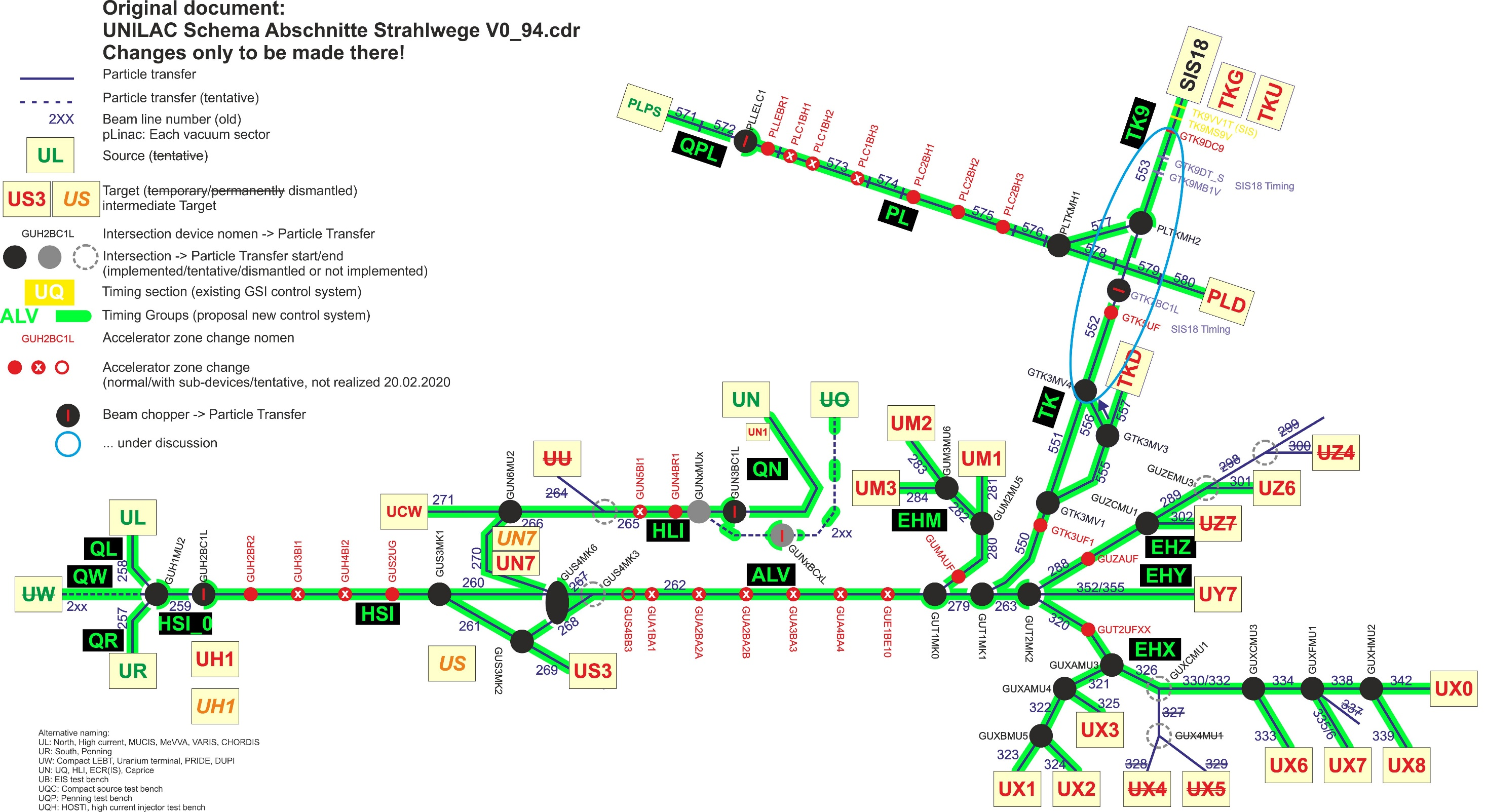 Figure: Overview on UNILAC. Figure adopted from here. Click here for larger image.
Transfer Channel (TK)
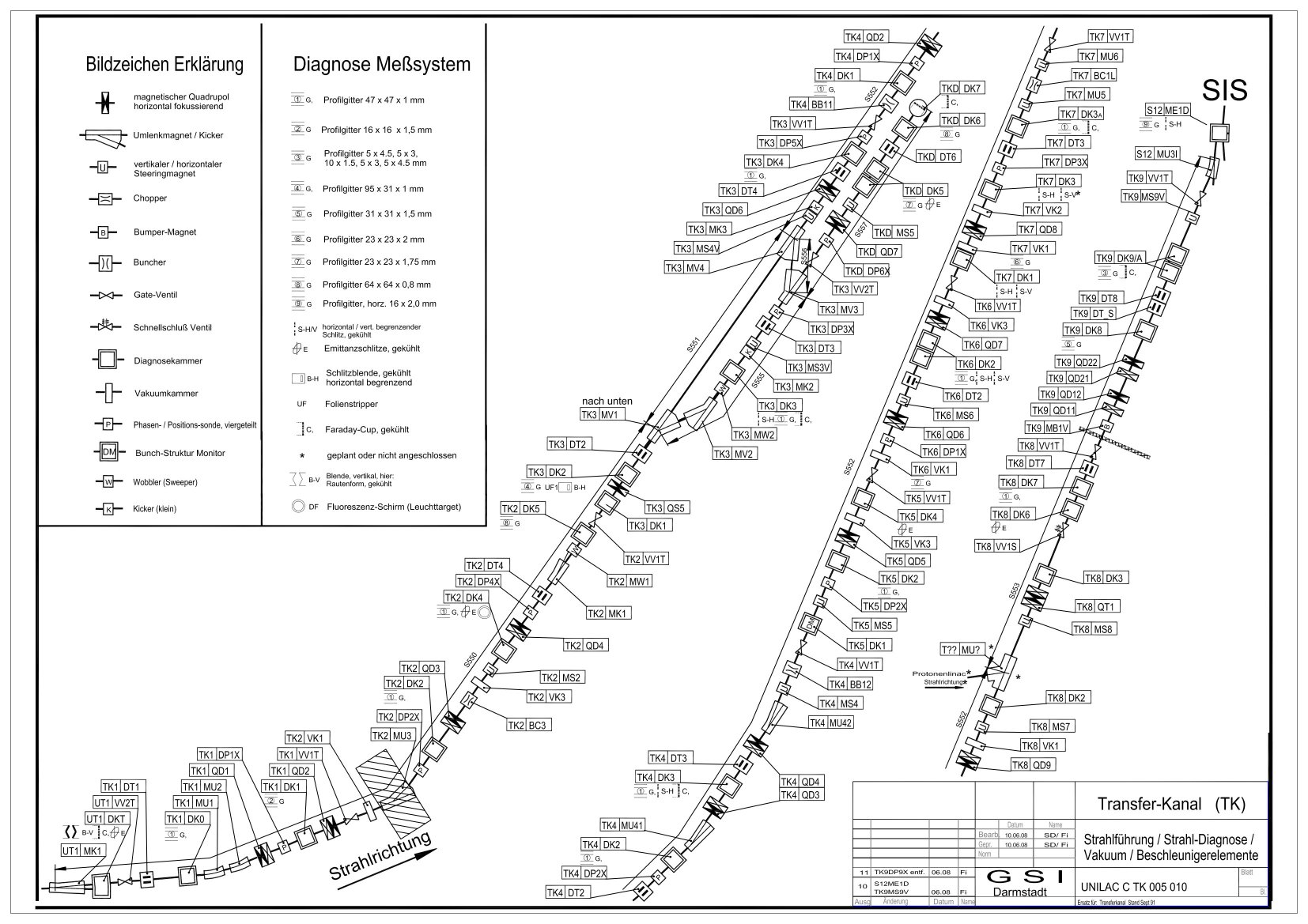 Figure: Overview on Transfer Channel between UNILAC and SIS18. The merging magnet 'PLTKMH2' from the pLinac is indicated as 'T??MU?'. Figure adopted from Accnomen Wiki. Click here for larger image.
SIS18, ESR, GSI-HEBT ('HEST')
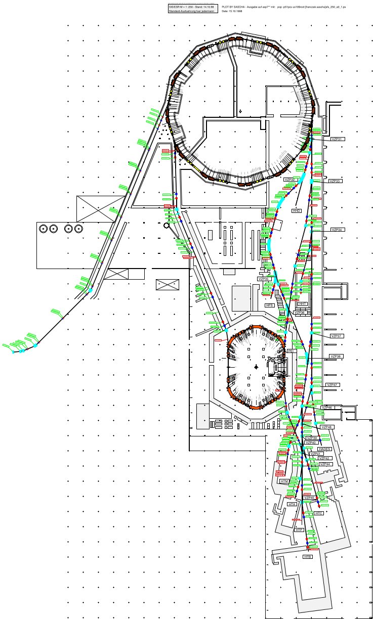 Figure: (Outdated) overview on the GSI facility and some optic elements (figure by Benno and others provided through Regine Pfeil, GSI). Click here for larger image.
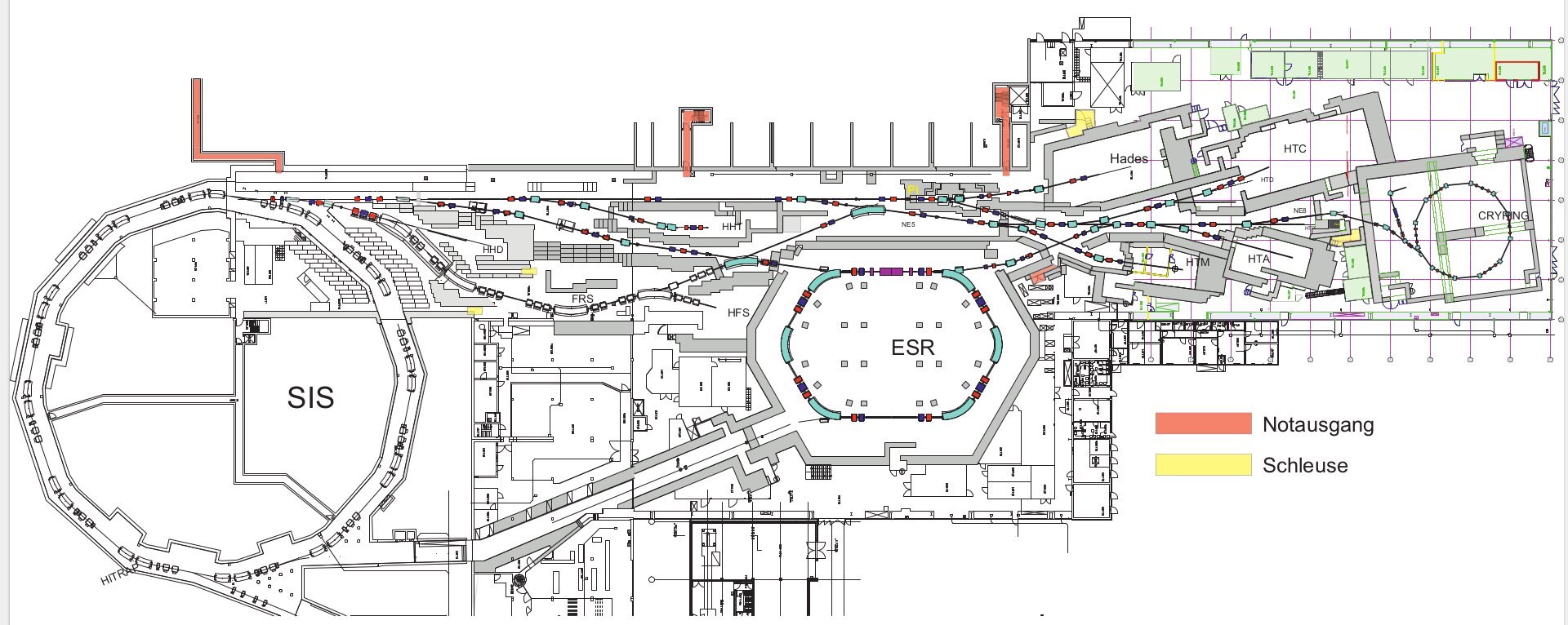 Figure: (Updated but less detailled) overview on the GSI facility and some optic elements (figure by uknown author, GSI). Click here for larger image.
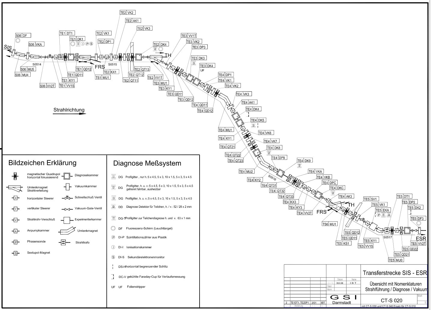 Figure: Transer line from SIS18 to ESR. Figure adopted from Accnomen Wiki. Click here for larger image.
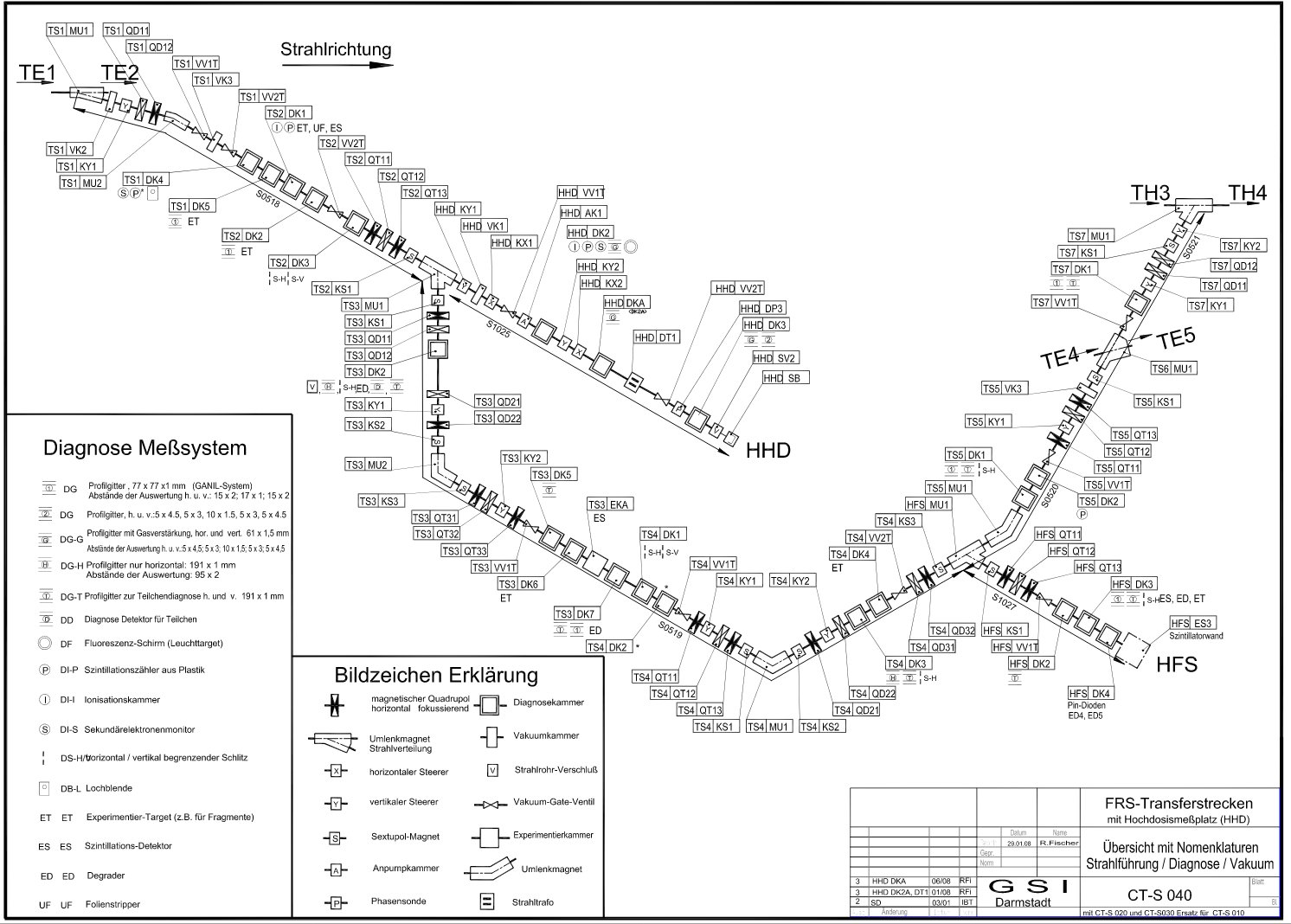 Figure: Transer lines FRS (HHT). Figure adopted from Accnomen Wiki. Click here for larger image.
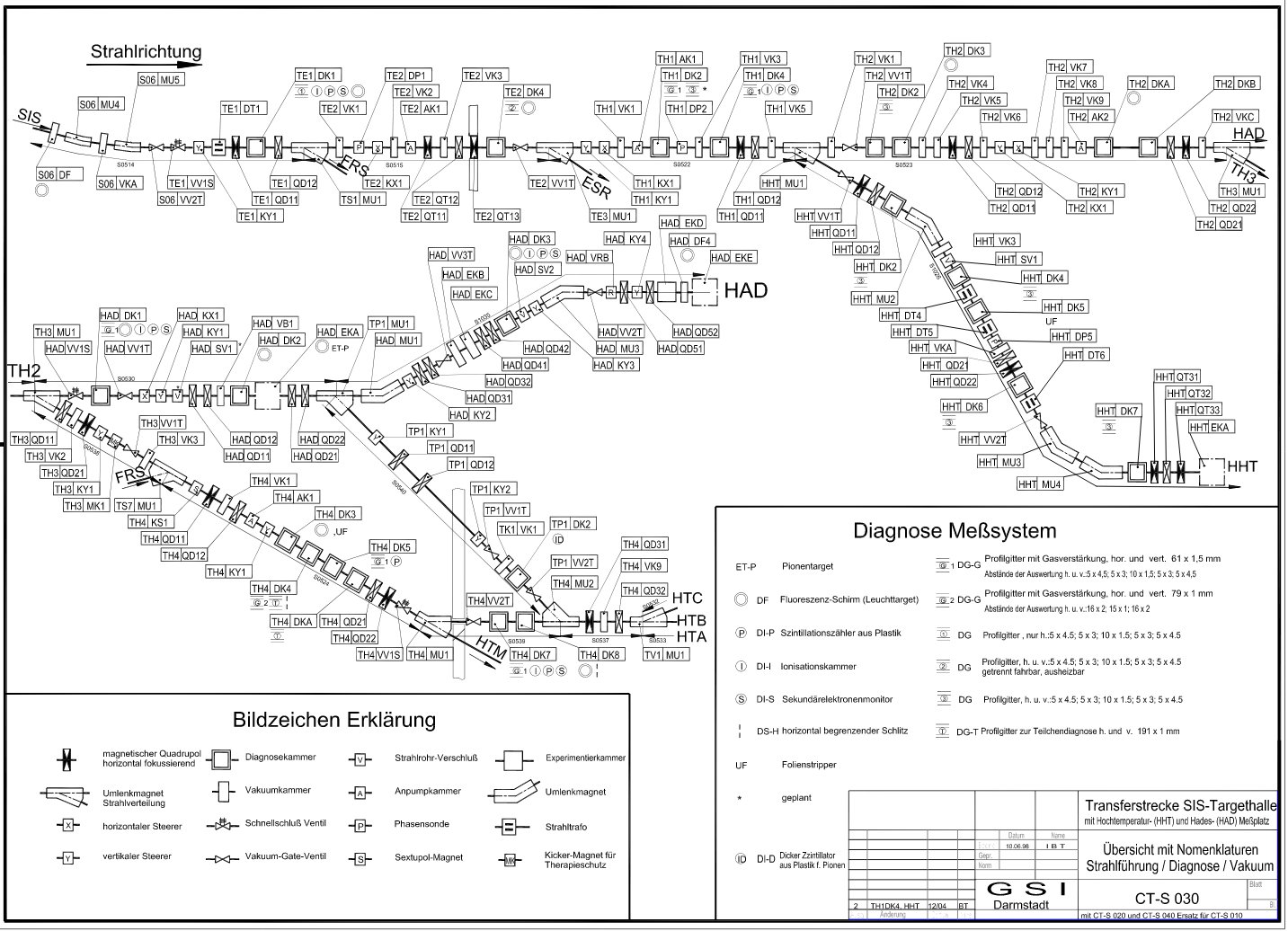 Figure: Transfer line from SIS18 to target hall (HHT and HAD). Figure adopted from Accnomen Wiki. Click here for larger image.
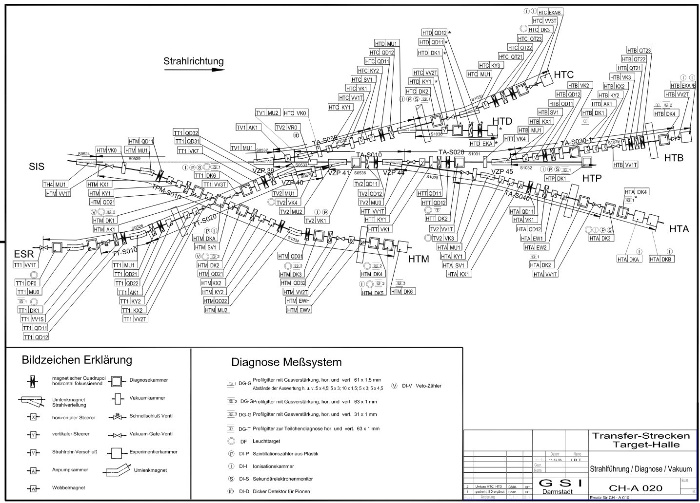 Figure: Transfer lines target hall. Figure adopted from Accnomen Wiki. Click here for larger image.
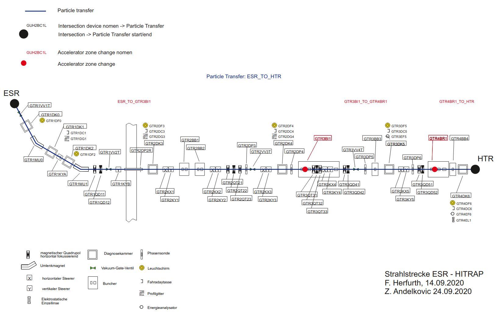 Figure: Transfer line from ESR to HITRAP.
CRYRING
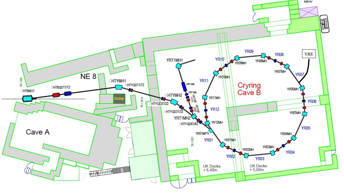 Figure: Overview on CRYRING (figure provided through Frank Herfurth, GSI)
NE Zones
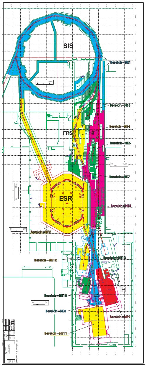 Figure: Overview on the NE areas (safety zones) at GSI (figure by some people provided through Regine Pfeil, GSI). Click here for larger image.
pLinac
 Figure: Overview on pLinac. The merging magnet 'PLTKMH2' into the Transfer Channel (TK, section 8) is indicated as 'PLTK' (figure provided through Accnomen Wiki, GSI)
-- DietrichBeck - 04 April 2025
 | I | Attachment | Action | Size | Date | Who | Comment |
|---|---|---|---|---|---|---|
| |
CRYRING_GID_A.jpg | manage | 198 K | 2016-07-07 - 15:49 | UnknownUser | arrangement of some GIDs for CRYRING |
| |
CRYRING_OVERVIEW_FH.jpg | manage | 130 K | 2019-08-14 - 14:17 | UnknownUser | overview on CRYRING |
| |
FRS_rf2.jpg | manage | 272 K | 2018-03-15 - 09:34 | UnknownUser | transfer lines FRS (HHD) |
| |
GSI-overview-DINA3-1.pdf | manage | 437 K | 2019-01-25 - 10:11 | UnknownUser | plan of parts of GSI facility (unknown source) |
| |
GSI_Anlagen_HE_mod.jpg | manage | 210 K | 2017-12-13 - 16:14 | UnknownUser | plan of parts of GSI NE areas (adopted from Regine...) |
| |
GSI_Anlagen_HE_mod.pdf | manage | 307 K | 2017-12-13 - 16:15 | UnknownUser | plan of parts of GSI NE areas (adopted from Regine...) |
| |
GSI_WithOILOpenCaves.jpg | manage | 425 K | 2019-05-15 - 14:37 | UnknownUser | gsi for public |
| |
SISTH.jpg | manage | 316 K | 2018-03-14 - 13:42 | UnknownUser | transfer line from SIS18 to target hall (HHT and HAD) |
| |
TE.jpg | manage | 208 K | 2018-03-15 - 09:23 | UnknownUser | transfer line SIS18 to ESR |
| |
THalle.jpg | manage | 304 K | 2018-03-15 - 09:37 | UnknownUser | transfer lines target hall |
| |
TK_8b.jpg | manage | 351 K | 2018-02-20 - 09:17 | UnknownUser | plan of parts of Transfer Channel (TK) |
| |
benno_plan_ SIS u ESR_20160331_A0_2.jpg | manage | 177 K | 2017-12-13 - 16:12 | UnknownUser | plan of parts of GSI facility (adopted from Benno, Regine...) |
| |
benno_plan_ SIS u ESR_20160331_A0_2.pdf | manage | 1 MB | 2017-12-13 - 16:13 | UnknownUser | plan of parts of GSI facility (adopted from Benno, Regine...) |
| |
groups.png | manage | 609 K | 2025-04-04 - 11:08 | DietrichBeck | overview on timing groups |
| |
gsi-overview.jpg | manage | 299 K | 2019-01-25 - 10:07 | UnknownUser | plan of parts of GSI facility (unknown source) |
| |
timingGroup_ESR_to_HTR.png | manage | 199 K | 2021-07-22 - 13:13 | UnknownUser | transfter to HITRAP |
| |
unilac.png | manage | 2 MB | 2023-08-22 - 14:14 | UnknownUser | simplified UNILAC overview |
Edit | Attach | Print version | History: r58 < r57 < r56 < r55 | Backlinks | View wiki text | Edit wiki text | More topic actions
Topic revision: r58 - 2025-04-04, DietrichBeck
 Copyright © by the contributing authors. All material on this collaboration platform is the property of the contributing authors.
 Ideas, requests, problems regarding GSI Wiki? Send feedback | Legal notice | Privacy Policy (german)


