WR-ZEN aka SSK
Introduction
The timing team (TOS) operates a couple of distinct White Rabbit networks. The most important one is a network called
production, that is
connected to a GSPDO and moreover phase-locked to BuTiS. Other networks serve other purposes as testing, integration systems and local operations. The motivation behind using the WR-ZEN is to lock the grander master clocks of the other White Rabbit networks to the
production network. The WR-ZEN is connected to the production network as a White Rabbit slave. It generates PPS and 10 MHz signals. These can be used as input to grand master White Rabbit switches of other White Rabbit networks.
Presented here are some tentative measurements that have been performed in summer 2019. The main motivation of this test is to analyze how well the outputs of a WR-ZEN can 'follow' a White Rabbit switch, that serves as a grand-master clock to which the WR-ZEN is directly connected as a White Rabbit slave.
It is expect that WR-ZENs 10 MHz signals on the 'A' and 'B' outputs perform better then the 'C' and 'D' outputs used for PPS signals; the 'C' andn 'D' outputs are generated from the FPGA only, while the 'A' and 'B' outpus are derived from a PLL (when using proper settings).
Equipment and Presentation
Equipment
- White Rabbit Switch 1 (WRS1); it is connected to the production network and produces a PPS reference signal
- White Rabbit Switch 2 (WRS2); it is used as a grand master of a secondary White Rabbit network; it requires PPS and 10 MHz signals as input
- White Rabbit Switch 3 (WRS3); it is connected to WRS1
- WR-ZEN
- 2 PEXARIA timing receiver (PEXARIA1, PEXARIA2); they produce PPS signals generated by a VDHL based clock generator
- 1 TR-AMC timing receiver; it produces PPS or 10 MHz clock signals generated by a VDHL based clock generator
- oscilloscope; 10GS/s sampling rate; 1 GHz analog bandwidth
The WR-ZEN is used to generate 10 MHz and PPS clock signals
- WR-ZEN TP-32BNC
- connected to WRS1 via SFP0
- AB_xPPS mode disabled
- outputs A and B
- 10 MHz signal
- fdelay 5000 ps
- output C and D
- PPS signal
- fdelay 0 ps
- 1 MOhm termination
All cables have identical length to about 1 cm.
Tables
The meaning of the columns is the following
- channel of scope
- device @ clock source, output
- signal type
- average offset value relative to WRS1, PPS out
- minimum offset value
- maximum offset value
- 'worst case window', this is the difference between maximum und minimum offset
- standard deviation
- number of samples
The values in columns 4,5, 6 and 8 are direct readings from the oscilloscopes display of 'measurement with statistics'.
Setup 1 - Connected to WRS1
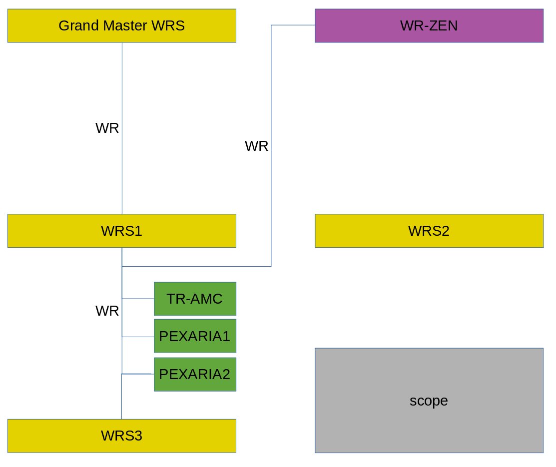
 Figure:
 WRS-ZEN, WRS3, TR-AMC, PEXARIA1 and PEXARIA2 are all directly connected to WRS1 via White Rabbit links. The cables connecting the outputs to the oscilloscope are not shown.
| channel |
device |
signal |
offset ave [ns] |
offset min [ns] |
offset max [ns] |
window [ns] |
sdev [ns] |
# of samples |
| 1 |
WRS1, PPS out |
PPS |
ref |
ref |
ref |
ref |
ref |
ref |
| 2 |
TR-AMC @ WRS1, OUT3 |
PPS |
7.842 |
7.729 |
7.954 |
0.225 |
0.037 |
612 |
| 2 |
WRS3 @ WRS1, PPS out |
PPS |
0.121 |
0.029 |
0.211 |
0.182 |
0.031 |
692 |
| 3 |
WR-ZEN @ WRS1, BNC 'C1' |
PPS |
-7.217 |
-7.331 |
-7.078 |
0.253 |
0.038 |
612 |
| 4 |
WR-ZEN @ WRS1, BNC 'C8' |
PPS |
-7.371 |
-7.507 |
-7.228 |
0.279 |
0.037 |
612 |
| 3 |
WR-ZEN @ WRS1, BNC 'D1' |
PPS |
-6.906 |
-7.036 |
-6.795 |
0.241 |
0.036 |
602 |
| 4 |
WR-ZEN @ WRS1, BNC 'D8' |
PPS |
-6.901 |
-6.997 |
-6.766 |
0.231 |
0.036 |
602 |
| 3 |
WR-ZEN @ WRS1, BNC 'A1' |
10 MHz |
7.888 |
7.653 |
8.048 |
0.395 |
0.046 |
602 |
| 4 |
WR-ZEN @ WRS1, BNC 'A8' |
10 MHz |
7.920 |
7.683 |
8.088 |
0.405 |
0.047 |
602 |
| 3 |
WR-ZEN @ WRS1, BNC 'B1' |
10 MHz |
7.202 |
7.006 |
7.344 |
0.338 |
0.048 |
692 |
| 4 |
WR-ZEN @ WRS1, BNC 'B8' |
10 MHz |
7.256 |
7.051 |
7.400 |
0.349 |
0.049 |
692 |
| 2 |
TR-AMC @ WRS1, OUT1 |
PPS |
7.870 |
7.748 |
7.973 |
0.225 |
0.038 |
605 |
| 2 |
TR-AMC @ WRS1, OUT2 |
10 MHz |
57.878 |
57.769 |
57.976 |
0.207 |
0.027 |
602 |
| 3 |
PEXARIA1 @ WRS1 |
PPS |
11.226 |
11.098 |
11.326 |
0.228 |
0.039 |
605 |
| 4 |
PEXARIA2 @ WRS1 |
PPS |
11.305 |
11.190 |
11.420 |
0.230 |
0.039 |
605 |
Table: Measured values. See text above for explanation. The values 'TR-AMC @ WRS1, OUT3' are measured to check reproducibility.
Discussion
Only the measured values 'windows' and 'sdev' are discussed. The average offset is not of interest here.
Compared to the other devices, the measured values of WRS3 are the best ones.
The measured values 'windows' and 'sdev' of the timing receivers are slightly worse than the ones from WRS3. However, the values tend to be better if timing receivers are compared to each other and not to WRS1 (see also
this publication).
The measured values of the WR-ZEN (low precision outputs) C1..D8 are in the same order of magnitude as for the timing receivers.
The measured values of the WR-ZEN (high precision outputs) A1..B8 are slightly worse compared to the low precision outputs; this is funny.
Setup 2 - Connected to WRS2 Using WR-ZEN as Clock Source
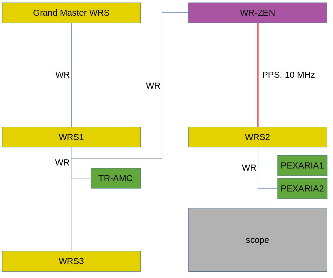
 Figure:
 WRS2 is set-up as a grand master. The PPS and 10 MHz
refclock signals from WR-ZEN are used (C1-PPS, A1-10MHz) as inputs.
Table: Measured values. See text above for explanation. The values 'TR-AMC @ WRS1, OUT3' are remeasured to check reproducibility.
Discussion
Compared to the case of WRS3 (that has a White Rabbit link to WRS1), the values 'window' and 'sdev' of WRS2 are slightly degraded.
Compared to the other devices, the values of WRS2 are the best ones.
Compared to the case where the timing receivers are directly connected to WRS1, the values of the PEXARIA timing receivers are degraded by about a factor of 2. The 'worst case' value is still better than one nanosecond.
Setup 3 - Connected to WRS2 Using TR-AMC as Clock Source
Remark: This measurement was done just for curiosity. Instead of a WR-ZEN, a standard TR-AMC timing receiver is used to produce the PPS and 10 MHZ refclock signals.
 Figure:
 WRS2 is set-up as a grand master. The PPS and 10 MHz
refclock signals from TR-AMC are used (OUT1-PPS, OUT2-10MHz) as input.
Table: Measured values. See text above for explanation. The values 'TR-AMC @ WRS1, OUT3' are remeasured to check reproducibility
Discussion
Compared to the case where WR-ZEN has been used as a clock source, the values are in the same order of magnitude and only slightly degraded.
The 'worst case' value of the PEXARIAs is still better than one nanosecond.
Conclusion
The idea is to derive 10 MHz and PPS clocks from a 'reference' White Rabbit network and to use these as reference clocks for White Rabbit switches in Grand Master mode. By this, distinct White Rabbit networks can be locked to each other AND they are completely isolated in terms of Ethernet.
Two possibilities have been evaluated. First using a WR-ZEN from 7Sols, second a TR-AMC timing receiver.
When measuring PPS signals of connected nodes relative to a PPS signal of rhe 'reference' network, the numbers investigated have been standard deviation and 'worst case window'. As a result, these numbers degenerate by about a factor of two. When comparing WR-ZEN and TR-AMC, the results obtained with the TR-AMC are slightly worse.
As a handwaving consistency check, one can quadratically add the values of 'window' or 'sdev'.
| device |
sdev [ps] |
window [ps] |
| PEXARIA @ WRS1 |
39 |
228 |
| WRS2 (*) |
31 |
182 |
| WR-ZEN @ WRS1, A1 |
46 |
395 |
| calc quad sum |
68 |
491 |
| PEXARIA1 @ WRS2 |
79 |
500 |
Table: Consistency check by adding values quadratically. It is assumed that WRS2 has the same properties as WRS3 (*).
As shown in the table above, the values look reasonable. Turning this argument around, one can calculate how 'bad' the WR-ZEN is in terms of additional White Rabbit switch layers. If looking at the 'worst case window' one obtains 395^2 / 182^2 = 4.7. Thus, introducing the WR-ZEN degenerates the timing performance similar to introducing a couple of layers of White Rabbit switches.
The variation in the average (mean) offset values are interesting, especially when comparing the TR-AMC and PEXARIA timing receivers to each other (values change also for different FPGA images). However this shall be subject to a later investigation.
Long term stability has not been investigated.
--
DietrichBeck - 13 Sep 2019
 Figure: WRS-ZEN, WRS3, TR-AMC, PEXARIA1 and PEXARIA2 are all directly connected to WRS1 via White Rabbit links. The cables connecting the outputs to the oscilloscope are not shown.
 Figure: WRS2 is set-up as a grand master. The PPS and 10 MHz refclock signals from WR-ZEN are used (C1-PPS, A1-10MHz) as inputs.
 Figure: WRS2 is set-up as a grand master. The PPS and 10 MHz refclock signals from TR-AMC are used (OUT1-PPS, OUT2-10MHz) as input.
 Copyright © by the contributing authors. All material on this collaboration platform is the property of the contributing authors.

