|
|
You are here: GSI Wiki>TOS/Timing Web>TimingSystemAMCTestingAndCommissioning (2019-12-12, ahahn)
AMC Testing and Commissioning Guide
- AMC Testing and Commissioning Guide
- Required components for each uTCA device
- Additional Resources
- Preparation
- Important Steps
- Programming the CPLD
- Programming the FPGA
- Programming the USB Chip
- Configuring (and programming) the SPI Flash Chip
- Formatting the WR EEPROM (MAC address is stored here)
- Check White Rabbit
- Check EEPROM and set MAC
- Check IOs
- Check PCIe
- Check PCIe interrupts
- Check LEDs
- Check Buttons and Hex Switches
- Check Display
- Check debug port HPLA
- Check OneWire Devices
- Check OneWire Devices (eb-mon)
- AMC/uTCA Stuff
- Ideas for FAT
Required components for each uTCA device
- SFP (green/purple)
- LC cable and a white rabbit switch (Recommended: RUNNING AT LEAST VERSION 4.1, if you can afford this)
- Quartus (Version 16.0.0 Build 211 was used for this guide)
- USB cable (micro 2.0)
- Power supply (if you don't use a crate)
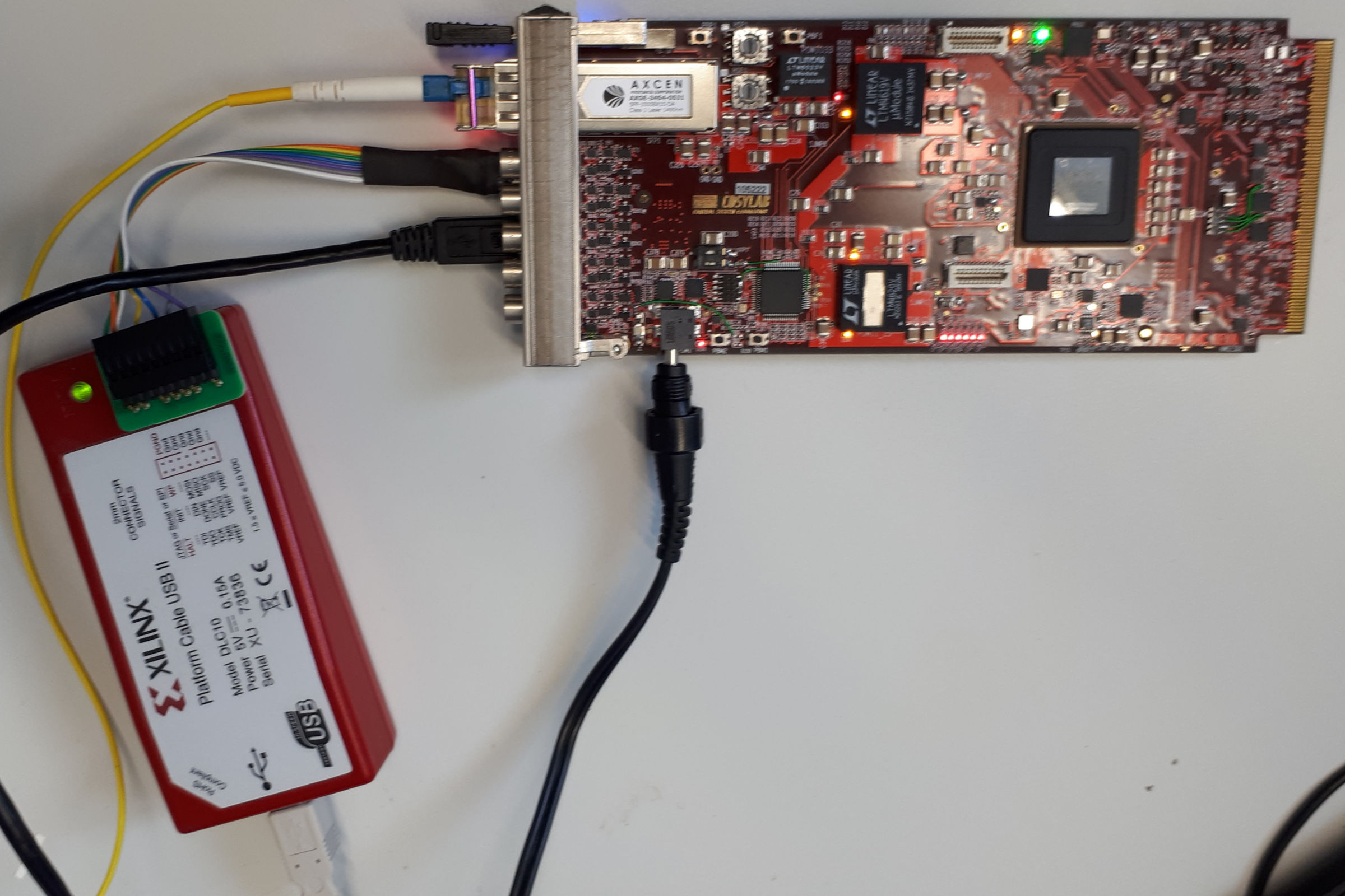
- Xilinx programmer (Platform Cable USB II, DLC10)
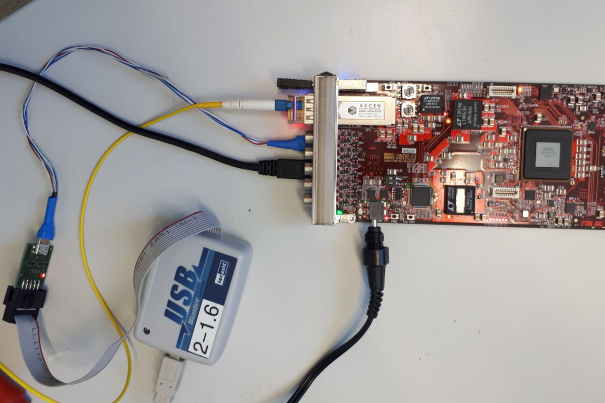
- Altera USD blaster + PROMO11 adapter
- 5x LEMO cable(s)
- N.A.T. NAMC EXT card (exposed backplane IOs)
- A second Timing Receiver with 5 LVTTL IOs (AMC, Exploder5, ...)
- MicroTCA crate ( ToDo: Add desired crate here )
- Libera crate ( ToDo: Add desired crate here )
- $dev is a placeholder for dev/ttyUSB[X] AND dev/wbm[X] - you have to test both interfaces!
- $saftlib-dev is a placeholder for tr[X], baseboard[X], ...
Additional Resources
Preparation
- Check out bel_projects
- $ git checkout https://github.com/GSI-CS-CO/bel_projects.git
- $ cd bel_projects
- $ git checkout tag doomsday-4.0.4
- $ ./fix-git.sh
- $ ./install-hdlmake.sh
- $ make
- (additional) $ make driver-install
- (additional) $ make etherbone-install
- (additional) $ make saftlib-install
- (additional) Use insmod to load the drivers oder restart
Important Steps
Programming the CPLD
- Turn on power
- Use Cosylab's boxed header to micro USB adapter and connect via JTAG (xilinx programmer)
- Run ISE
- Load project bel_projects/syn/gsi_microtca/cpld/microtca_prog.xise
- Process Menu => Implement Top Module
- Tools Menu => Impact
- Double-click Boundary Scan
- Control-I => microtca_prog.jed
- Operations Menu => Program
- Turn power off

Programming the FPGA
- Turn power on
- Connect JTAG via PROMO11 adapter
- Open Quartus and program the FPGA (or use the command line: quartus_pgm -c 1 -m jtag -o 'p;microtca.sof')
- (optional) Write this bit-stream into the SPI flash: eb-flash $dev microtca.rpd (in case USB and flash chip are already programmed)

Programming the USB Chip
- Run 'make' in bel_projects/ip_cores/etherbone-core/hdl/eb_usb_core
- Make sure, that no other timing receiver is attached by USB
- Erase the USB controller (as root): ./flash-fx2lp.sh -E
- Program the USB controller (as root): ./flash-fx2lp.sh
- Turn power off and on
Configuring (and programming) the SPI Flash Chip
- Program the FPGA again: quartus_pgm -c 1 -m jtag -o 'p;microtca.sof'
- Configure the SPI flash chip: eb-config-nv $dev 10 4
- [at room temperature] Write the bit-stream into the SPI flash: eb-flash $dev microtca.rpd (in case FPGA is not persistently programmed
- Turn power off and on
- [at high temperature > crate without cooling] Write the bit-stream into the SPI flash again: eb-flash $dev microtca.rpd
- Repeat 5. three times
Formatting the WR EEPROM (MAC address is stored here)
- Go to bel_projects/ip_cores/wrpc-sw/tools
- Run "make"
- ./eb-w1-write $dev 0 320 < sdb-wrpc.bin
Check White Rabbit
- eb-console $dev
- Type in "gui", white rabbit status should be: locked and calibrated
- Remove and apply the fiber cable five times and make sure WR locks again
- Press ESC to quit
- Power cycle the device and repeat step #3 -> Watch the WR LEDs (the receiver should synchronize again)
| Synchronization status should be: + Servo state: TRACK_PHASE + Phase tracking: ON You should also see 4 leds at the front panel: + red = traffic/no-link + blue = link + green = timing valid + white = PPS |
- Remove fiber cable
- Type in "mode master", node should be able to lock the PLL and become a master
Quit console - (optional) Test status via Saftlib $ saft-ctl $saftlib-dev -s
| Output should look like this: WR locked, time: 0x152c4f5bbfcf5528 receiver free conditions: 256, max (capacity of HW): 0(256), early threshold: 4294967296 ns, latency: 4096 ns |
Check External Reference Clock
- Provide a 10MHz clock (i.e. from a White Rabbit switch)
- Drive IO_CLKIN_EN to High $ saft-io-ctl $saftlib-dev -n IO_CLKIN_EN -d 1 (Note: In the foreseeable future it will work like this: $ saft-io-ctl $saftlib-dev -n IO5 -q 1)
- Open the White Rabbit console again and type in: mode master
- Check if WR is really locked (LED, eb-console -> GUI, generate clocks, ...)
- Additionally check if the system works with a 20MHz input clock too
- (optional) Turn off master mode (mode slave)
- (optional) Generate a clock on this and on another receiver and compare them
Check EEPROM and set MAC
- Run eb-console $dev
- (optional) Set MAC address for the device #xy: <<mac setp aa:bb:cc:dd:ee:ff, Control-C
- Check given MAC address
- Turn power off and on
- Run eb-console $dev
- Type in "mac", you should see the previously entered MAC address
- If you don't have a DHCP server, you can set an ip address by "ip set 192.168.100.xyz"
Check IOs
Front Panel IOs
- Get a second uTCA timing receiver (or a receiver with at least 5 LVTTL IOs)
- Connect IO1 (device #1) to IO1 (device #2) and so on... [IO1,IO2,IO3,IO4,IO5]
- Device #1: Turn output enable for the IOs on $ saft-io-ctl $saftlib-dev -n IO{1,2,3,4,5} -o 1
- Device #1: Start a clock on each IO $ saft-clk-gen $saftlib-dev -n IO{1,2,3,4,5} -f 10000000 0 (will generate a 10 MHz clock)
- Device #2: Snoop inputs $ saft-io-ctl $saftlib-dev -s
- Measure jitter and signal quality with a scope (FTRN specification should be matched)
Slew Rate
- Measure the slew rate with a scope (for EVERY IO), should be equal to Exploder5
IO Load Test
- Drive every IO with termination
- $ saft-io-ctl $saftlib-dev -n IO{1,2,3,4,5,...} -o 1 -t 0/1 -d 1
- Measure levels/voltage with a scope
Termination Test
- Drive every IO with and without termination
- Make sure that the switchable termination works
IO Bandwidth
- Generate a 200MHz clock (saft-clk-gen) and measure the clock with a scope
- Generate a 125MHz clock (with an additional receiver or reference device) and measure it with the ECA (saft-io-ctl snoop mode)
Output Enable Test
- Drive every IO with and without output enable
- Make sure you don't see a level change when output enable is turned off
- Check the LEDs, they should indicate every activity and the output enable status
uTCA 4 Clocks A B C D
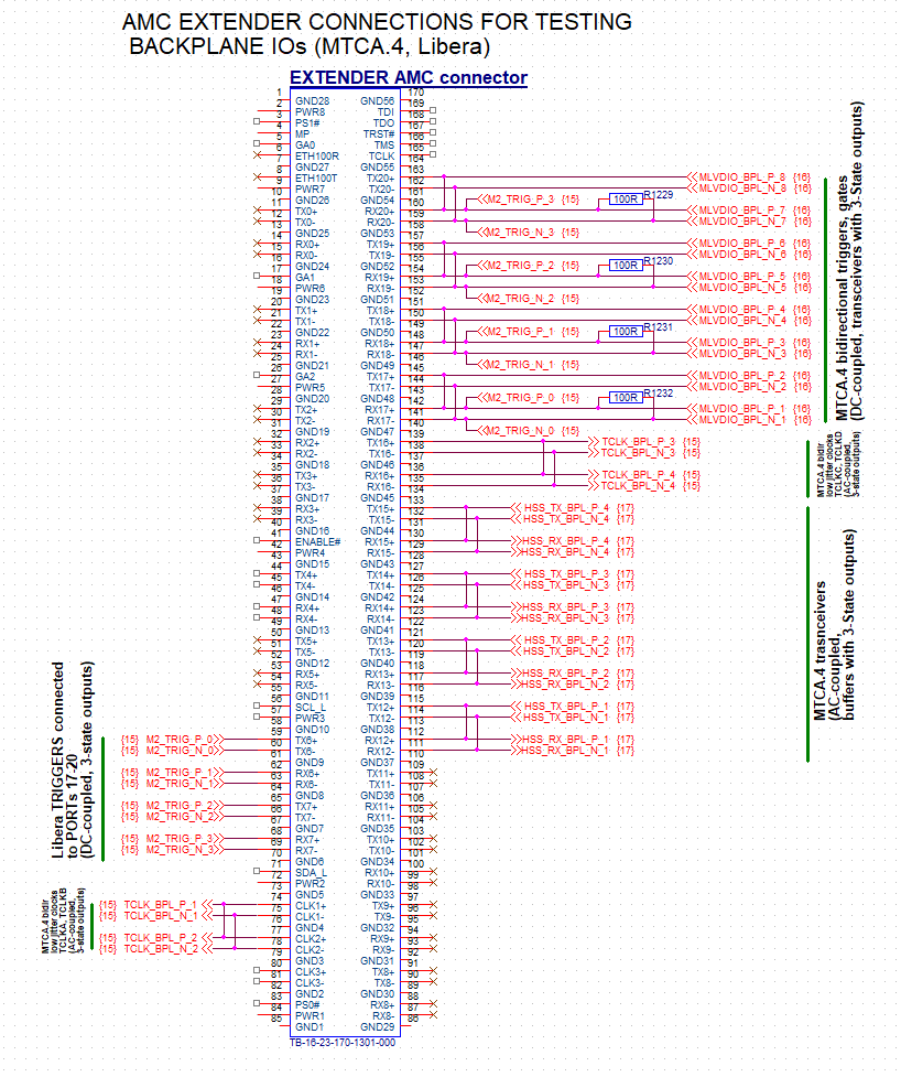
- Use the modified debug card (N.A.T. GmbH NAMC-EXT V1.5), which connects/loops the lines
- Turn on a clock and check it (siehe "Front Panel IOs")
- Measure jitter and signal quality with a scope (FTRN specification should be matched)
uTCA 4 PORT 17-20 Triggers
- Use the modified debug card (N.A.T. GmbH NAMC-EXT V1.5), which connects/loops the lines
- Turn on a clock and check it (siehe "Front Panel IOs")
- Measure jitter and signal quality with a scope (FTRN specification should be matched)
Libera Triggers
- Use the modified debug card (N.A.T. GmbH NAMC-EXT V1.5), which connects/loops the lines
- Turn on a clock and check it (siehe "Front Panel IOs")
- Measure jitter and quality with a scope


Check PCIe
- Try the following tools:
- eb-console $dev
- eb-info $dev
- eb-ls $dev
-
Write to internal shared ram and read it back:
- Get the LM32 shared ram address by eb-ls $dev
- Example output: 3.2 0000000000000651:81111444 84000 LM32-RAM-Shared
- Create a dummy file (which will be written into the ram): dd if=/dev/urandom of=foo bs=4k count=1;
- Write dummy file to the lm32 shared ram: eb-put $dev 0x84000 foo
- Get the data from the shared ram: eb-get $dev 0x84000/4096 bar
- Compare both files: cmp foo bar
- Both files should contain the same data
- Repeat this test in a loop... (recommended: 10 minutes)
Check PCIe interrupts
- Create your own schedule (or use the attached one -> schedule.txt)
- Start snooping for events: $ saft-ctl $saftlib-dev snoop 0 0 0 -x
- Inject events: $ saft-dm $saftlib-dev -fp -n 1 schedule.txt
- Verify that you got all events
Check LEDs
- $ saft-pps-gen $saftlib-dev -s
- Leave the application running and check all LEDs
Check Buttons and Hex Switches
- $ saft-io-ctl $saftlib-dev -s
- Start rotating switches (HSF1) => Check output of saft-io-ctl
- Start pushing buttons (PBF1) => Check output of saft-io-ctl
| IO . Edge . Flags .... ID ...................... Timestamp ........... Formatted Date --------------------------------------------------------------------------------------------------------- PBF Rising .... (0x0) 0xfffe000000000015 0x1532cdaf1fb0beb7 2018-05-28 12:09:35.666667191 PBF Rising .... (0x0) 0xfffe000000000017 0x1532cdaf24a84fe8 2018-05-28 12:09:35.750000616 |
Check Display
- cd bel_projects/tools/display
- make
- ./simple-display dev/ttyUSBx -s "Hello World!" -d 2
Check debug port HPLA
- To be defined
Check OneWire Devices
- Go to: tools/commissioning/onewire-scanner
- make
- run application: ./onewire-scanner dev/ttyUSB0
| Output should look like this (OWID should be slightly different): Scanning for OneWire controller(s) on $dev now... |
Check OneWire Devices (eb-mon)
- Check device with eb-mon
| root@MTCA-6P-PH4d:~# eb-mon dev/wbm0 -w0 -b0 -f0x28 0xbd0000091958c628 root@MTCA-6P-PH4d:~# eb-mon dev/wbm0 -w0 -t0 -f0x28 45.1875 |
AMC/uTCA Stuff
Program MMC flash
- Clone the firmware repository: $ git clone https://github.com/GSI-CS-CO/mtca_mmc_firmware.git
- Read anf follow README.md file
- Optional: LPC2136_FreeRTOS_CoreIPM.bin
Check MMC USB
- minicom -b 115200 -D /dev/ttyUSB0
- Press "i"
Check MCH and FTRN FRU info and sensors
- Connect to the MCH (USB: minicom -b 19200 -D /dev/ttyACM0)
Check PCIe Devices
- Run $ show_fru
| Device information: ---------------- FRU Device State Name ========================================== 0 MCH M4 NMCH-CM 3 mcmc1 M4 NAT-MCH-MCMC 5 AMC1 M4 CCT AM 902/411 8 AMC4 M4 CSL-MMC-WR <= ! Get number here [Dec. 2019] Name is now "FTRN" 40 CU1 M4 Schroff uTCA CU 50 PM1 M4 NAT-PM-AC600D 60 Clock1 M4 MCH-Clock 61 HubMod1 M4 MCH-PCIe ========================================== |
Check FRU Information
- Check FRU information: $ show_fruinfo 8
| --------------------------------------- FRU Info for device 8: --------------------------------------- Common Header : 0x01 0x00 0x00 0x01 0x07 0x0e 0x00 0xe9 --------------------------------------- Internal Use Area : - --------------------------------------- Chassis Info Area : - --------------------------------------- Board Info Area : at offs=8, len=48 Manufacturer(07) : Cosylab Board Name(08) : FTRN_AMC Serial Number(09) : 000000001 Part Number(04) : FTRN FRU file ID(07) : FTRNFRU --------------------------------------- Product Info Area : at offs=56, len=56 Manufacturer(07) : Cosylab Product Name(08) : FTRN AMC Product Number(05) : 00001 Part Version(02) : v3 Product Serial Number(06): 000001 Asset Tag(00) : - FRU file ID(07) : FTRNFRU Customer Info-0 (53) : git▒ub.co▒▒{▒Z1▒▒▒!▒▒rPxZ1▒uDZ1 Customer Info-1 (00) : - Customer Info-2 (00) : - Customer Info-3 (00) : - Customer Info-4 (00) : - --------------------------------------- Multi Record Area : at offs=112 Record(0): Type ID=0xc0, PICMG Record ID=0x19, offset=0x000, len=21 AMC Point-to-Point record: AMC Slot 4, OEM GUID Count = 0 Record Type = AMC, len=21 Channel Descriptor count = 1 Channel(0): Port[4 - - -] Link Descriptors: size=5 Link 0 of Channel 0: lanes[0..3]=[1000], PCIe, Gen 1, no SSC, Grp=0x0, Match=0x1 Record(1): Type ID=0xc0, PICMG Record ID=0x16, offset=0x015, len=11 Module Current Requirements Record: Current Draw: 1.5 A Record(2): Type ID=0xc0, PICMG Record ID=0x00, offset=0x020, len=10 Header=buf 0x41b30a68 len 5 c0 82 05 75 44 Data =buf 0x41b30a6d len 5 5a 31 00 00 00 --------------------------------------- |
Check Sensors
- Check sensors: $ show_sensorinfo 8
| Sensor Information for FRU 8 / AMC4 ================================================================== # SDRType Sensor Entity Inst Value State Name ------------------------------------------------------------------ 0 MDevLoc 0xc1 0x64 CSL-MMC-WR 1 Full 0xf2 0xc1 0x64 0x01 Hot Swap 2 Full Voltage 0xc1 0x64 12.155 V ok +12V Payload 3 Full Voltage 0xc1 0x64 3.344 V ok +3.3V Mng 4 Full Temp 0xc1 0x64 43.86 C ok Temp Inlet 5 Full Temp 0xc1 0x64 43.43 C ok Temp Outlet 6 Full 0xc0 0xc1 0x64 0x01 V 0x00 FPGA CONFIG 7 Full 0xc0 0xc1 0x64 0x01 V 0x00 CONF DONE 8 Full 0xc0 0xc1 0x64 0x00 V 0x00 LIBERA TRIGGER 9 Full 0xc0 0xc1 0x64 0x00 V 0x00 MTCA4 TRIGGER 10 Full 0xc0 0xc1 0x64 0x00 V 0x00 JTAGSW POS 11 Compact 0xf0 0xc1 0x64 0x10 HS 008 AMC4 ------------------------------------------------------------------ |
Check PCIe Speed
- Run: $ show_link_state
- Look for this Output: AMC 4 Port 4 is PCIe - x1 - 2,5 GT/s
- Verify it comes from ID 8: $ show_link_state 8 4 => AMC 4 Port 4 is PCIe - x1 - 2,5 GT/s
Stop and Start Unit
- $ shutdown 8
- $ fru_start 8
IPMI FRU Test
- Check FRU and sensors via IPMI tools
Ideas for FAT
General Ideas
- Generate a different frequency (saft-clk-gen) on every IO and make sure WR still works
- Check for crosstalk, mix inputs and outputs
- PCB delay measurement (compare to exploder5)
- Check 5V input on front panel IOs
Libera
- Check iTech "Low-Jitter-Clock", 1ps jitter should be achieved
- 24h PCIe write and read test
- Multiple modules (TR) at the same time in a crate
How-Swap (Propoal DB, to be reviewed by AH and DS)
- uTCA
- operate AMC FTRN in a uTCA crate; use power supply from 'White List'
- pull handle at FTRN
- check FTRN can be removed (FPGA no longer powered)
- remove FTRN
- insert another FTRN
- check FTRN is again fully powered
- (restart PCIe driver)
- check FTRN is reachable via 'eb-ls'
- Libera
- operate AMC FTRN in a Libera crate
- pull handle at FTRN and make sure nothing happens:
- check FTRN remains powered
- check FTRN remains reachable via 'eb-ls'
- release or push-back handel at FTRN
- check FTRN remains powered
- check FTRN remains reachable via 'eb-ls'


| I | Attachment | Action | Size | Date | Who | Comment |
|---|---|---|---|---|---|---|
| |
LPC2136_FreeRTOS_CoreIPM.bin | manage | 110 K | 2019-12-12 - 13:33 | UnknownUser | |
| |
altera_prog_utca.jpg | manage | 123 K | 2018-05-08 - 15:55 | UnknownUser | |
| |
front_io_test.jpg | manage | 166 K | 2018-05-08 - 15:58 | UnknownUser | |
| |
nat-ext-amc.png | manage | 70 K | 2019-12-05 - 15:47 | UnknownUser | |
| |
schedule.txt | manage | 960 bytes | 2018-05-28 - 15:37 | UnknownUser | |
| |
xiling_prog_utca.jpg | manage | 364 K | 2018-05-04 - 10:37 | UnknownUser |
Please login to edit this topic
Topic revision: r27 - 2019-12-12, ahahn
Ideas, requests, problems regarding GSI Wiki? Send feedback | Legal notice | Privacy Policy (german)