You are here: GSI Wiki>TOS/BunchBucket Web>BunchBucketDocumentation>BunchBucketHowTo>BunchBucketHowCLI (2024-03-12, dbeck)Edit Attach
User Interfaces
Table of ContentsIntroduction
This page just describes the user interfaces. All command line interfaces (CLI) just require a keyboard. Navigation is done by simple keys, < cursor > keys + < Return > key or < page up/down > keys.User and Betrieb
B2B Monitor
Launching-
Launcher->Verschiedenes->B2B Monitor - ... and resize terminal window to 150x24
-
d: toggles the displayed data (kicker or ring-hf); default: kicker -
u: toggles the displayed units (nanoseconds or degree); default: degree -
i: toggles display (show/hide) of inactive patterns/transfers; default: active patterns for all rings-
0: toggles display (show/hide) of transfer with SIS18 as origin -
1: toggles display (show/hide) of transfer with ESR as origin -
2: toggles display (show/hide) of transfer with CRYRING as origin
-
-
d: toogle data display: 'kicker values' or 'DDS values' -
h: prints help -
q: exits the CLI
 Figure: B2B Monitor. The header line just displays the version of the CLI. The bottom line displays the key shortcuts and current local time. Information about ongoing transfers is listed in a table; each line shows a complete transfer from origin to destination.
See text for details.
In the example shown above, three patterns are active.
 - 'SIS18_FAST_HHD_MD_sc...' is a fast extraction from SIS18 to HHD
- 'SIS18_FAST_Au_ESR' is a fast extraction from SIS18 into ESR as coasting beam
- 'ESR_CRYRING_COOLER_R...' is a fast extraction from ESR into CRYRING as coasting beam
B2B System Status too (click).
| Column | What | Remark |
|---|---|---|
| pattern name | name of pattern | |
| t_last [UTC] | time of last extraction | no updates although pattern is active? Check B2B System Status (start via Launcher) |
| origin | machine extracting the beam | the following columns contain data of the extracting machine |
| sid | Sequence ID of the fast extraction process | |
| kick(er) set (*) | set-value of trigger deadline relative to rising edge of h=1 group DDS signal | |
| ... trg | measured value of trigger deadline relative to rising edge of h=1 group DDS signal | The measured should not deviate by more than 1 ns from the set-value; a systematic deviation points to either wrong frequency value of h=1 group DDS or BuTiS/White Rabbit are not synchronized; frequent jumps of the deviation indicate a problem with the group DDS |
| ... offs(e)t | measured value of the ParamModi parameter 'Kicker Offset' at the kicker electronics | in case of ERROR no signal was detected at the output of the kicker electronics; typical reasons are a) malfunction of kicker control electronics (check with 'DeviceControl) b) with mode 'bunch to bucket' the beating period might be to long (> 16 ms) c) wrong set-values of kicker or the b2b system: try a 'Vollversorgung' via ParamModi |
| ... start | measured offset of the rising edge of the kicker magnet probe signal | in case of UNKWN , the reason could be a) kicker has not fired (check with digitizer) or b) an issue with the detection at the b2b system |
| ... fltop | measured length of kicker magnet probe signal (= length of flattop) | in case of UNKWN , the reason could be a) kicker has not fired (check with digitizer) or b) an issue with the detection at the b2b system [1] |
| dest(inatio)n | destination of the extracted beam | the following columns contain data of the injection machine |
| sid | Sequence ID of the injection process | |
| phase set (*) | set-value of phase difference between extraction and injection ring | only for mode bunch-2-bucket (not for coasting beam) |
| ... get | measured phase difference of the two h=1 group DDSs for the case of true bunch-2-bucket | in case of coastg the beam is injected as coasting beam |
| kick(er) set, trg, start, fltop | see extraction machine (above) | |
| ... dOffs(e)t | measured time difference of the signals at the output the kicker electronics at extraction and injection machine | |
| ... ToF | measured time difference of the signals of the kicker magnet probes (rising edge) at extraction and injection (falling edge) | this should be correlated to the time-of-flight between kickers |
| h1gDDS [Hz] | frequency of h=1 group DDS on flat-top | in case of ERROR , the b2b system detects no signal from the group DDS; try 'Vollversorgung' via ParamModi; possible failure of data supply of the DDS; maybe a hardware error? |
| ... ext/inj | indicates data of extraction or injection ring | |
| ... set | set value; this is the set value of the DDS, which might differ slightly from the LSA value (32bit resolution of DDS) | |
| ... get | measured value and its estimated uncertainty | |
| ... diff | deviation between measured- and set-value | |
| ... v/c | beam velocity in units of speed-of-light | |
| prob | a comparator is used to detect the rising edge of the of the kicker magnet probe signal; here, the trigger level is shown (experimental feature) | |
| ... ext/inj | indicates data of extraction or injection ring | |
B2B Monitor . Set values marked by '*' are informative only and have a reduced precision of about one per mille.
[1] Please note: Due to the extremely poor probe signal at CRYRING, the flat-top length of the CRYRING kicker signal is most likely not correct.
B2B System Status
Launching-
Launcher->Verschiedenes->B2B System Status - a standard 80x24 terminal window is fine
-
s: display status text -
< digit 0..9, a..f >: clears diagnostic information of the corresponding system -
h: prints help -
q: exits the CLI
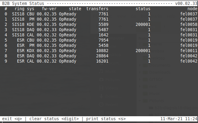 Figure: Overall system status. The header line just displays the version of the CLI. The bottom line displays the key shortcuts and current local time. The status of the B2B components is listed in a table. Shown are system number (column 1), ring machine (column 2), system name (column 3), version (column 4), main state (column 5), number of transfers the system has been involved (column 6), status (column 7) and host system (column 8). See text for details.
The figure above shows the overall sytem status of the B2B system. The system shown are the embedded realtime components CBU (Central B2B Unit), PM (Phase Measurement) and KD.. (Kicker and Diagnostics). Non-realtime systems DAQ (Acquisition of set- and get-values) and CAL (data analysis) are shown too.
If everything is ok, all systems shall have a value '1' in the column 'status'. However, reality is different as shown in the typical situation in the above below, where the lm32 firmware SIS18 and ESR kickers yields an error. This is due to the fact, that in rare cases the kickers are not fired (for whatever reason).
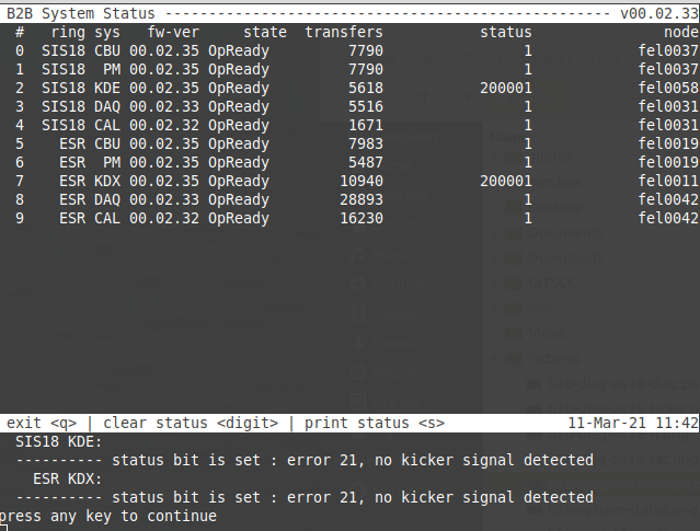 Figure: B2B System Status. Pressing key 's' display more detailed status information.
Pressing key 's' will print detailed status information. Important: If an (error) status is detected, it will be remembered until the diagnostic information is cleared by pressing '< digit 0..9, a..f >'. Thus, this is only a summary of all errors of all patterns that have happend in the past and is it not possible to see which pattern is causing trouble.
Errors
List of common errors (click).Expert
Viewer CLI
The CLI displays a variety of things but does not have a menu structure. The viewer can be controlled by pressing keys on the keyboard:-
b: toggles display of parameters for *b*unch-to-bucket transfer (if applicable) -
d: toggles display of Group DDS phase *d*iagnostic -
r: toggles display of *r*f diagnostic -
k: toggles display of *k*icker diagnostic -
s: toggles display of *s*tatus of the B2B system; this is mainly interesting for experts -
q: quits the viewer -
c: clears all recorded data; this is useful- when settings have changed
- to 'reset' statistical data after a serious of erroneous measurements
- Important: This is not a local operation but sends a command to the analysis process for the transfers of this extraction machine and SID.
-
act: actual value of the latest transfer -
ave: average values of all transfers of all recorded data -
sdev: standard deviation of all transfers -
minmax: minimum and maximum values observed for all transfers
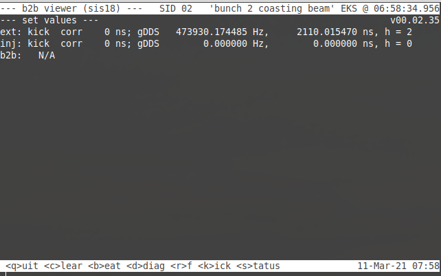 Figure: Viewer shows set-values. The head line displays the ring machine where the transfer starts (here: sis18), Sequence ID (SID) of the extraction process, B2B mode and UTC time of the latest EVT_KICK_START. The bottom line displays a quick help for using the viewer as well as current local date and time. Details see text.
The figure above shows the set-values that are displayed when starting the viewer.
 - The 1st line
set valuesjust displays the version number of the viewer. - The 2nd line
ext:displays the correction value [ns] of the extraction kicker, frequency of h=1 Group DDS for the extraction (here: SIS18), Group DDS period (= revolution time of beam in the ring) [ns] and the harmonic number (not relevant for mode 'B2C'). Please note that the true values of the Group DDS differ from the LSA values [1]. - The 3rd line
inj:displays the correction value [ns] of injection kicker (frequency and period of the Group DDS of the injection machine (here: ESR) and the harmonic number are not relevant for for this mode.
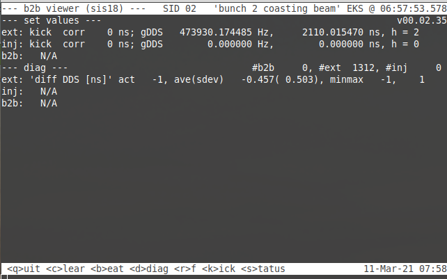 Figure: Viewer shows diagnostic values for extraction. Details see text.
When pressing the key 'd' on the keyboard, the viewer toggles display of diagnostic values for extraction and injection (only for real 'bunch to bucket'). This is the most important diagnostic information as it shows how well actual the actual phase of the the h=1 Group DDS matches the predicted value at the moment of transfer. In the ideal world, extraction and injection yield the value '0' (= perfect match, no deviation) and the value for 'bunch to bucket' yields the value set by the operators.
 - 1st line
diag: number of measurements for 'bunch to bucket', extraction ring and injection ring; in mode 'bunch to coasting beam', there is no value for injection, as the phase of the h=1 Group DDS of the injection ring is not relevant in this mode - 2nd line
ext:: measured value for the h=1 Group DDS of the extraction ring (value 'ext_ddsOff') - 3rd line
inj:: measured value for the h=1 Group DDS of the extraction ring (only relevant for mode 'bunch to bucket', value 'inj_ddsOff') - 4th line
b2b:: measured phase difference between the two Group DDSs (phase injection - phase extraction, value 'phaseOff').
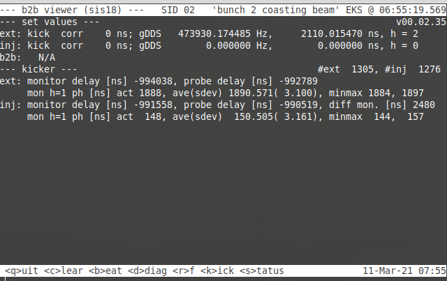 Figure: Diagnostic values for kickers. Here, the kickers are not triggered by the B2B system but by the so-called 'Timing Generator'. Details see text.
Pressing key 'k' displays diagnostics for the kickers. The figure above shows the typical situation when the B2B is not operative and the kickers are triggered by the Timing Generator of SIS18. A measurement is done when two conditions are fulfilled: First the B2B system sends a timing message for a kicker trigger. Second, the B2B system detects a TTL signal at the output of the kicker electronics in the kicker room.
 - 1st line
kicker: number of measurements for extraction (here: SIS18) and injection (here: ESR) kicker. The numbers are different, as the ESR injection kicker does not always fire. - 2nd line
ext: monitor: delay of monitor (electronics out) and probe (kicker magnet) relative the kicker trigger of the B2B system. Note: When the B2B system is used, positive values of a few microseconds are shown (values 'ext_dKickMon' 'ext_dKickProb'). - 3rd line
mon h=1: delay of the kicker electronics output with respect to the preceding rising edge of the h=1 Group DDS of the extraction ring. If the extraction is locked to the Group DDS, a narrow distribution around a fixed mean value is expected values ('ext_monRem...'). - 4th line
inj: monitor: same as the 2nd line but with an additional value; 'diff mon.' shows the difference of the monitor signals of extraction and injection kicker. Here, the signal of the injection (ESR) is 2.48 us later than the one of the extraction (SIS18) (values 'inj_dKickMon' 'inj_dKickProb' 'inj_dKickMon - ext_dKickMon'). - 5th line
mon h=1: same as 3rd line. Please note: Also these values are measured with respect of the h=1 Group DDS of the extraction ring (values 'inj_monRem...').
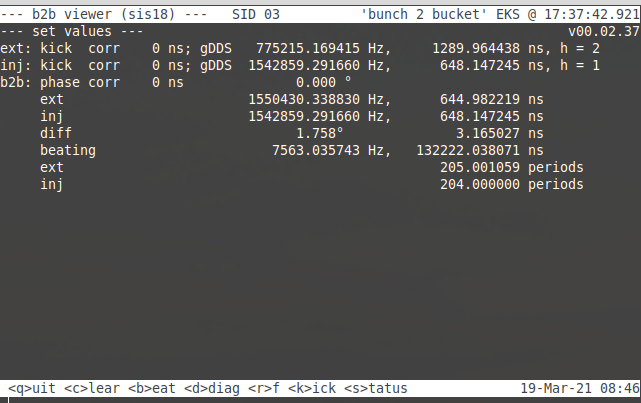 Figure: 'Set-values' for mode 'Bunch 2 Bucket'. Details see text.
Pressing key 'b' displays values for mode 'Bunch to Bucket' (if applicable). There is no measurement but the values are directly derived from the set-values.
 - 1st line
phase corr: set-value for relative phase between the two h=1 Group DDS of the two rings; the value is given in nanoseconds and degree (relative to h=1 of extraction). - 2nd line
ext: rf-cavity frequency and period of extraction ring at flat top - 3rd line
inj: rf-cavity frequency and period of injection ring at injection - 4th line
diff: differenc of the two cavity frequencies in degree (per rf-cycle) and nanoseconds - 5th line
beating: beating frequency and period - 6th line
ext: number of rf-cycles within one beating period at extraction - 7th line
inj: number of rf-cycles within one beating period at injection
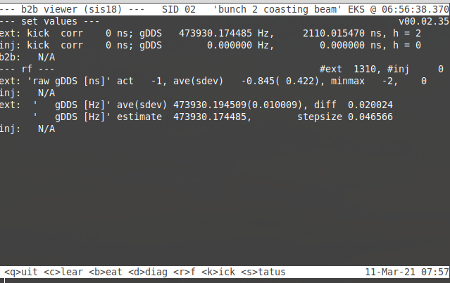 Figure: Diagnostic values for the RF h=1 Group DDS. Details see text.
Upon pressing key 'r', diagnostic values for the h=1 Group DDS are displayed. Theses values stem from an additional phase measurement that is done approximately 20 ms after EVT_KICK_START, where the measured phase is compared to the expected value.
 - 1st line
rf: number of measurements done for extraction and injection. A measurement for injection is only done in mode 'bunch to bucket'. - 2nd line
ext raw: raw values for the h=1 Group DDS of the extraction ring; offset between expected and actual value; in the ideal case, no deviation is observed (values 'ext_rfOff...') - 3rd line
inj (raw): same as the 2nd line but for the h=1 Group DDS of the injection ring (values 'inj_rfOff...') - 4th line
ext ave: measured frequency (mean value and standard deviation) of the Group DDS of the extraction ring based on the raw value. The difference to the set-value is given too (values 'ext_rfNue...'). - 5th line
estimate: best estimate on the actual 'true' DDS value. In the ideal case, this value matches the set-value exactly. A difference of +/- 46mHz might still be ok. If the difference is higher, s.th. is wrong:- missing data supply of h=1 Group DDS
- mismatch in set-values between ParamModi and B2B
- BuTiS and White Rabbit not locked to each other
- lines 6+7: same as lines 4+5 but for injection, (values 'inj_rfOff...' 'inj_rfNue...')
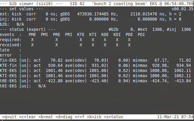 Figure: Expert status information for the B2B system. See text for details.
Pressing key 's' yields that status display of the B2B system. This information is mainly interesting for experts to diagnose potential problems in the system itself.
 - 1st line
status: number of measurements for extraction, injection and mode 'bunch to bucket' - 2nd line
events: abbreviation event names for timing messages used by the B2B system, see here - 3rd line
required: an 'X' marks the message types required for the actual operation mode of the B2B system (here: bunch to coasting beam) - 4th line
received: an 'X' marks the messages that have actually been received. This shall match the previous line (values 'flagEvtRec'). - 5th line
late: an 'X' marks messages that are received 'late'. This would indicate a malfunction and shall not happen (values 'flagEvtLate'). - 6th line
error: an 'X' marks messages where s.th. went wrong (values 'flagEvtErr').- missing message
- late message
- an error flag has been raised by the sender of the message
- data in the message are out of range
- lines 7..12: statistical information on processing and message flight times (values 'doneOff'..'ktiOff'), see here.
- values shall have a defined distribution around a constant average
-
KTE-EKSandKTI-EKSshall have box-shaped distributions within the following windows- modes 'bunch to extraction' and 'bunch to coasting beam': 1000..1000 + RF period us (here: RF period has a set-value of 2.11 ns)
- mode 'bunch to bucket': 1000..1000 + beating period us (usually a few milliseconds)
Bonus: Kicker Failures
If one is interested in statics on kicker operations, one can check the Viewer CLI as shown below.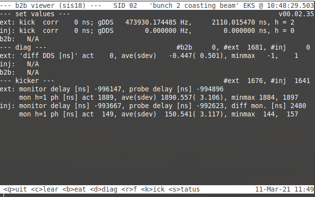 Figure: Pressing keys 'd' and 'k' displays diagnostics on phase match and kickers. Please note the difference in numbers of execution.
As displayed in the figure above, it is interesting to compare the numbers of execution.
 -
diag:- 1681 transfers
-
kicker:- 1676 detected kicks at SIS18 extraction
- 1641 detected kicks at ESR injection
- false measurement by the B2B system
- Timing Generator does not trigger or problem with signal transmission from 'Elektronikraum BG 2 009' to kicker rooms
- failure of kicker electronics in kicker rooms
Control CLI
This is an expert tool for development purposes in case the LSA and FESA are not present. The settings of the CLI are stored pesistently on disk.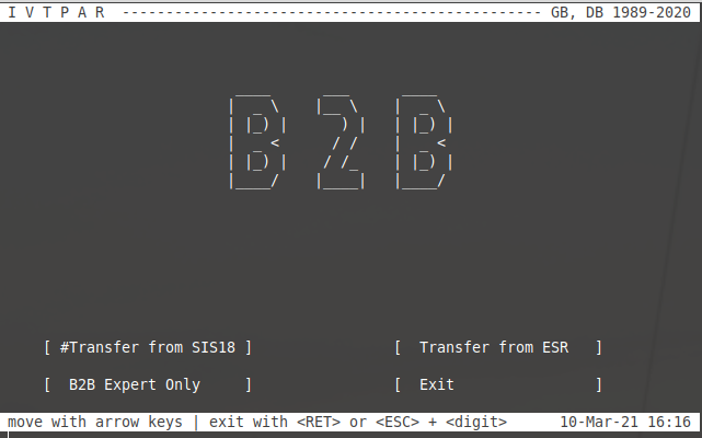 Figure: Welcome screen.
The figure above shows the welcome screen of the control CLI.
 - choose SIS18
- to configure fast extractions from SIS18
- to configure transfer from SIS18 to ESR
- choose ESR
- to configure fast extraction from ESR
- (to configure transfer from ESR to CRYRING)
- choose Exit to quit
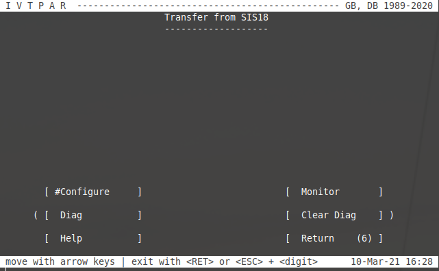 Figure: Main screen for SIS18.
The figure above shows the main screen to configure the SIS18 CBU. Choose 'Configure' or 'Return'.
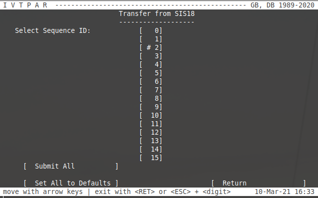 Figure: SIS18: Select Sequence ID that should be configured.
The figure above shows the dialog to select the Sequence ID for configuration.
 - 'SID 2' has been selected by using the < cursor > keys. Pressing the < Return > key will open the dialog for configuration.
- choose 'Submit Sll' to supply all Sequence IDs 0..15 (similar to 'Vollversorgung' with ParamModi)
- choose 'Set All to Defaults' will set the settings for SID 0..15 to default values (= trigger kicker upon EVT_KICK_START).
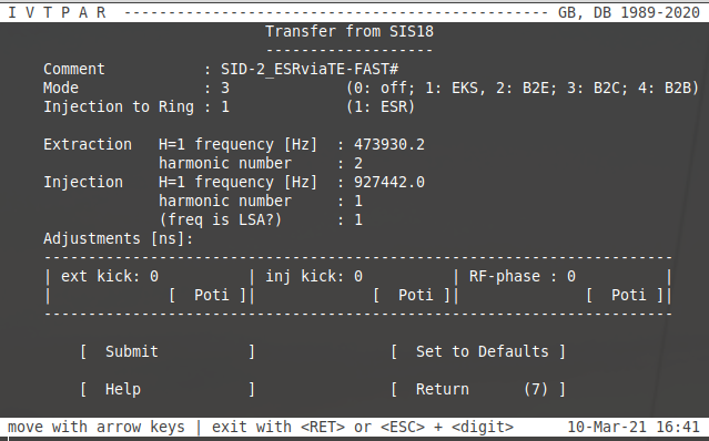 Figure: SIS18: Configuration dialog for a given SID.
The figure above shows the configuration dialog for a given Sequence ID. Here, a transfer from SIS18 to ESR is configured in mode 'bunch to coasting beam'. In this mode, the settings for harmonic number and ESR injection frequency are just dummies.
- Comment: Just a comment of your choice. It is recommended to keep the SID as part of the comment.
- Set-Values: Please have a look at the meaning of set-values.
- Poti: Can be selected for easy on-line trimming of values.
- Submit: Submits the set-values to the CBU.
- Set to Defaults: Sets all values to defaults.
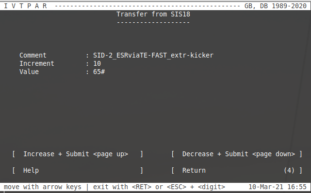 Figure: SIS18: Trimming of extraction kicker timing via < page up/down > keys. Here, the value for incrementing or decrementing is set to 10 ns.
-- DietrichBeck - 24 October 2023
 | I | Attachment | Action | Size | Date | Who | Comment |
|---|---|---|---|---|---|---|
| |
b2b-diag-sis18-b2b.png | manage | 64 K | 2021-03-19 - 08:49 | UnknownUser | b2b-diag sis18 b2b values |
| |
b2b-diag-sis18-diag.png | manage | 56 K | 2021-03-11 - 08:17 | UnknownUser | b2b-diag sis18 diag values |
| |
b2b-diag-sis18-kicker.png | manage | 68 K | 2021-03-11 - 09:38 | UnknownUser | b2b-diag sis18 kicker values |
| |
b2b-diag-sis18-rf.png | manage | 64 K | 2021-03-11 - 10:08 | UnknownUser | b2b-diag sis18 rf values |
| |
b2b-diag-sis18-set.png | manage | 46 K | 2021-03-11 - 08:02 | UnknownUser | b2b-diag sis18 set value |
| |
b2b-diag-sis18-status.png | manage | 84 K | 2021-03-11 - 11:04 | UnknownUser | b2b-diag sis18 status |
| |
b2b-system-status-error.png | manage | 121 K | 2021-03-11 - 11:44 | UnknownUser | b2b-system-status with error display |
| |
b2b-system-status.png | manage | 97 K | 2021-03-11 - 11:26 | UnknownUser | b2b-system-status |
| |
b2b-ui-sis18-config.png | manage | 55 K | 2021-03-10 - 16:42 | UnknownUser | b2b-ui sis18 config |
| |
b2b-ui-sis18-kicker-failures.png | manage | 77 K | 2021-03-11 - 11:50 | UnknownUser | b2b-diag sis18 kicker failures |
| |
b2b-ui-sis18-main.png | manage | 31 K | 2021-03-10 - 16:31 | UnknownUser | b2b-ui sis18 main |
| |
b2b-ui-sis18-poti.png | manage | 38 K | 2021-03-10 - 16:56 | UnknownUser | b2b-ui sis18 poti |
| |
b2b-ui-sis18-sid.png | manage | 35 K | 2021-03-10 - 16:39 | UnknownUser | b2b-ui sis18 select sid |
| |
b2b-ui-welcome.png | manage | 32 K | 2021-03-10 - 16:18 | UnknownUser | b2b-ui welcome |
| |
b2b_transfer_monitor.png | manage | 44 K | 2024-03-12 - 14:44 | UnknownUser |
Edit | Attach | Print version | History: r24 < r23 < r22 < r21 | Backlinks | View wiki text | Edit wiki text | More topic actions
Topic revision: r24 - 2024-03-12, dbeck
 Copyright © by the contributing authors. All material on this collaboration platform is the property of the contributing authors.
 Ideas, requests, problems regarding GSI Wiki? Send feedback | Legal notice | Privacy Policy (german)


