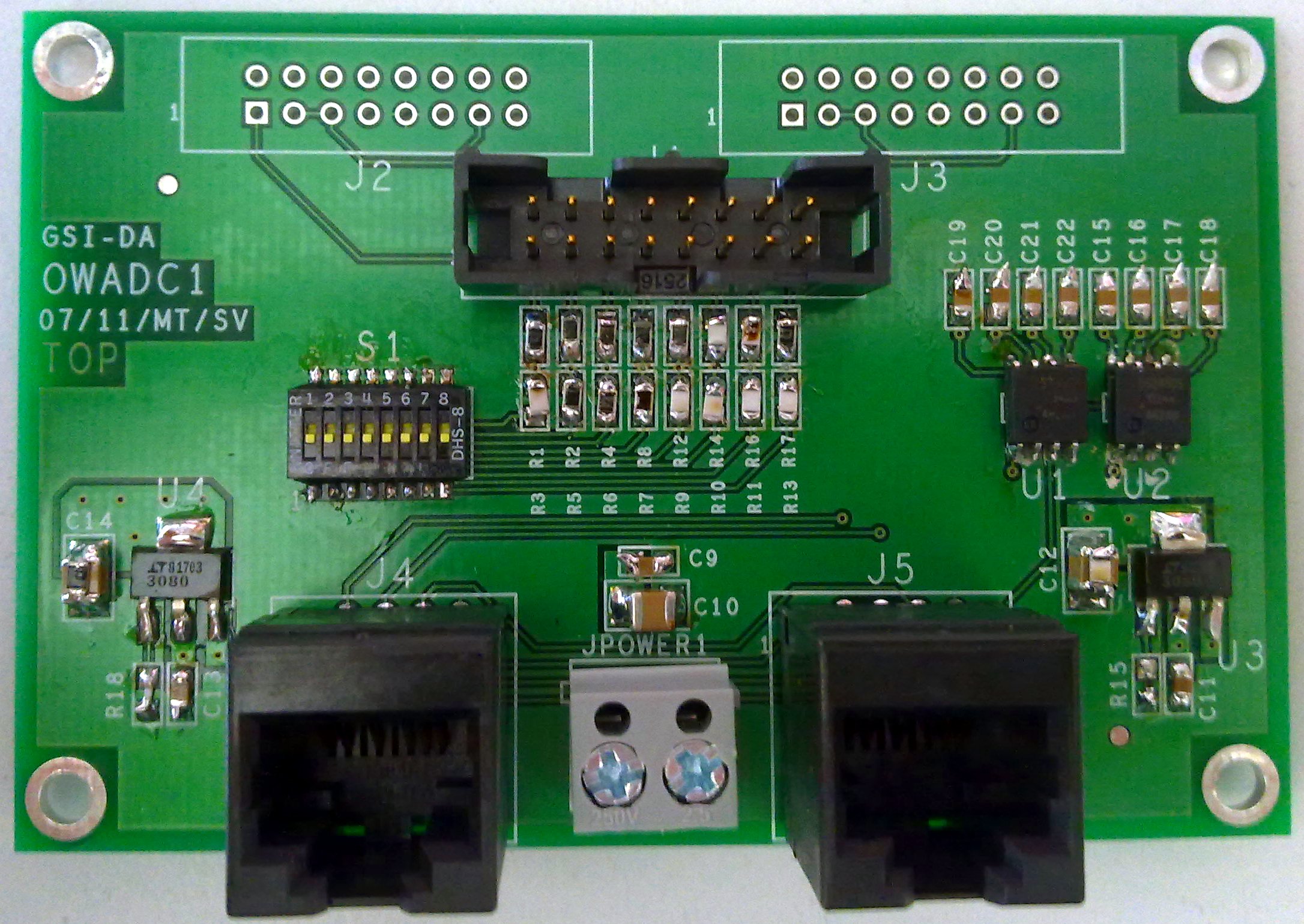
OWADC1 - 1-wire 8-channel ADC board
Introduction

OWADC1 is a small, compact board designed by M.Traxler and S.Voltz (GSI/EE) to provide an 8 channel, max. 16bit ADC to be accessed by 1-wire protocol
Documentation
Layout
1-wire ADC
RC time
The inputs of the ADCs have capacities of
100 nF connected to
GND (
C15 ... C22 ).
- Apparently the input resistance of the ADC seems to be around 1010 Ω, therefore the time constant τ is around 1000s, improving noise resilience, but reacting quite slow to rapid changes.
- NOTE: we deduced those numbers the other way around: having 100nF, we saw a decay time of a 3V input value (~36000 adc counts) to 0 less than 1000, to take more than 10 minutes. Details on purpose.
- The datasheet says: 1MOhm.
- To decrease τ smaller capacities should be used.
known 1-wire IDs
new list/new numbers
| Board Number/Name/ID |
Position |
ID |
user |
| |
|
|
|
| |
|
| 001 |
U1 |
20CE0210000000D8 |
|
| U2 |
20D6021000000022 |
| 002 |
U1 |
20011C10000000BD |
|
| U2 |
20D62B1000000029 |
| 003 |
U1 |
20832E100000003E |
|
| U2 |
20D7021000000015 |
| 004 |
U1 |
20340710000000B7 |
|
| U2 |
20F81B1000000008 |
| 005 |
U1 |
207A2E10000000DA |
|
| U2 |
20792E1000000083 |
| 006 |
U1 |
20520710000000C6 |
|
| U2 |
20380710000000CA |
| 007 |
U1 |
20E814100000003C |
|
| U2 |
203E071000000078 |
| 008 |
U1 |
20CD2B100000008A |
|
| U2 |
20051C1000000061 |
| 009 |
U1 |
20DC14100000000D |
|
| U2 |
20D41410000000AC |
|
| Board Number/Name/ID |
Position |
ID |
user |
| 010 |
U1 |
20C0C30F00000086 |
|
| U2 |
20D2C30F000000B3 |
| 011 |
U1 |
2058C70F00000089 |
|
| U2 |
20C0C90F0000003B |
| 012 |
U1 |
200B9F0F00000055 |
|
| U2 |
2037A70F0000007F |
| 013 |
U1 |
20609F0F0000006E |
|
| U2 |
20ADC30F0000000F |
| 014 |
U1 |
201A9F0F00000039 |
|
| U2 |
20679F0F000000EB |
| 015 |
U1 |
20BDA60F00000097 |
|
| U2 |
20279E0F00000053 |
| 016 |
U1 |
20D4A80F00000060 |
|
| U2 |
20FBC00F000000DD |
| 017 |
U1 |
202FC90F00000036 |
|
| U2 |
203FA70F000000DE |
| 018 |
U1 |
20E8C30F00000091 |
|
| U2 |
202CC90F0000006F |
| 019 |
U1 |
20989E0F00000070 |
|
| U2 |
20FFC40F0000001E |
|
| Board Number/Name/ID |
Position |
ID |
user |
| 020 |
U1 |
20799C0F000000ED |
|
| U2 |
20DFC10F0000007A |
| 021 |
U1 |
2050C50F000000AB |
|
| U2 |
20149F0F0000002A |
| 022 |
U1 |
2062C70F000000AB |
|
| U2 |
2065C70F0000002E |
| 023 |
U1 |
20F4C30F000000B7 |
|
| U2 |
205CC70F00000055 |
| 024 |
U1 |
20139F0F000000AF |
|
| U2 |
2046C50F00000042 |
| 025 |
U1 |
204AC50F0000003F |
|
| U2 |
20579F0F00000006 |
| 026 |
U1 |
2056A10F00000017 |
|
| U2 |
20F0A80F0000000A |
| 027 |
U1 |
20E8A80F000000F0 |
|
| U2 |
20DCC10F00000023 |
| 028 |
U1 |
20E5C10F00000058 |
|
| U2 |
20FBC30F00000093 |
| 029 |
U1 |
20EEC30F00000023 |
|
| U2 |
200C9F0F000000D0 |
|
Notes and Remarks
- Make sure to have (at least) 1 pull-up resistor of about 3.3kΩ on the data line of the 1-wire bus to the power
VDD.
- Recommended to have it at the master, e.g. at HadCon's connector
JDINOUT2.
Future/Extensions/Wish list
- 10 pin 1-wire connector:
- pin layout compatible to JDINOUT of HadCon and HadCon2
- but with a switch/dial (?) to connect internal 1-wire bus to one of the available 6 positions
- switch for allowing/blocking (default) connection to external VDD of HadCon(2)
- alternative:
- 2 pin connector (screws/clamps) connecting only data and ground line
- RJ-45 connectors
Applications
--
PeterZumbruch - 2020-07-27

 OWADC1 is a small, compact board designed by M.Traxler and S.Voltz (GSI/EE) to provide an 8 channel, max. 16bit ADC to be accessed by 1-wire protocol
 Copyright © by the contributing authors. All material on this collaboration platform is the property of the contributing authors.

