You are here: GSI Wiki>EPS Web>AdaptiveControlUnit>NecessaryHardwareModifications>ICMTriplinePropagation (2020-11-20, DerekSchupp)Edit Attach
ICM tripline propagation
Problem description:If one interlock is masked, it is possible to turn on the power converter even if the local HW trip-line is pulled.
This because the circuit involved in the trip-line propagation is not working as it should be (it reacts on the trip-line memorized falling edge, but it is frozen in trip-line ok status after the reset command from the MFU independently of the HW trip-line status). Problem solution:
The problem solution involves HW and FW changes:
- HW : For FG660_055 is necessary to:
- The ICM FG660_055 needs only the R160 resistor value to be changed, from 33 Ohm to 0 Ohm.
- HW : For FG660_056is necessary to:
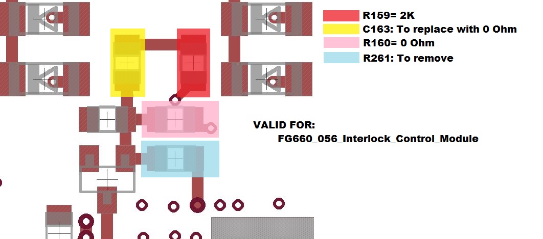
- The ICM FG660_056 needs the same changes done for the newer ICM version (_57, _058, _059),
but the parts names are different. Please take a look at the picture below.
- The ICM FG660_056 needs the same changes done for the newer ICM version (_57, _058, _059),

- HW : For FG660_057, FG660_058 and FG660_059 it is necessary to:
- Replace R159 with 2K resistor value
- Replace R160 with 0 Ohm resistor value
- Replace C73 with 0 Ohm resistor value
- Remove R167
- FW : The HW fixes don’t work without the ICM FW 7.3.1 and later FW release.
The release includes a three state buffer in combination with an open drain module to manage the USI_SLAVE_LOCAL_TRIPLINE_OK output pin.
During the reset command coming from the MFU, the three state buffer is enabled and the FPGA is able to close the HW trip-line circuit. As soon as the reset is released, the open drain module will drive the output pin (it is only able to pull down the output).
For all the other cases not mentioned above, it is always the local HW trip-line to drive the propagation. The steps to perform are the following:
- Apply the HW fixes as described above.
- Check with a multimeter if the components are properly soldered.
- Download the latest ICM firmware (at least ICM 7.3.1) to the FPGA ( it can be found here)
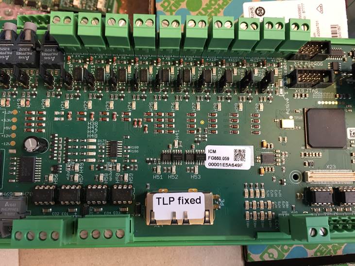
- Apply the TLP fixed (Trip Line Propagated) label as shown in the picture below.
 -- DerekSchupp - 2019-04-10
 Edit | Attach | Print version | History: r3 < r2 < r1 | Backlinks | View wiki text | Edit wiki text | More topic actions
Topic revision: r3 - 2020-11-20, DerekSchupp
 Copyright © by the contributing authors. All material on this collaboration platform is the property of the contributing authors.
 Ideas, requests, problems regarding GSI Wiki? Send feedback | Legal notice | Privacy Policy (german)
