You are here: GSI Wiki>TOS/BunchBucket Web>BunchBucketDocumentation>BunchBucketDocuments>BunchBucketTestsMeasurements>BunchBucketTestMeasurement3 (2021-02-22, dbeck)Edit Attach
November 2020: Dry Run
Table of ContentsIntroduction
In November 2020 the B2B system was tested during a dry run. The following main features were deployed- SIS18 and ESR kickers
- trigger kicker control electronics ('fire the kickers')
- basic data acquisition
- time of output signal of kicker control electronics
- time of kick by signal from kicker magnet probes
- distribution of acquired data in hard-real time via the timing network; delivery to the customer at 1ms after the kick
- integration into real accelerator schedule by listening from 'events' from the real Data Master
- modes
- trigger extraction kicker upon EVT_KICK_START
- fast extraction from a ring in sync with the RRF H=1 group DDS signal
- fast extraction of bunch from a ring and transfer to another ring ('bunch to coasting beam')
- no bunch to bucket
- simultaneous operation of CBUs at SIS18 and ESR
Setup
See here.Log
| date | time | what | remark |
|---|---|---|---|
| 2020-11-19 | SIS18 kicker, trigger at EVT_KICK_START, acquire signals | |
|
| increase energy of SIS18 kicker to a high value to check we have no issues with electronic noise | |
||
| 2020-11-23 | ESR kicker, trigger generated by B2B, acquire signals | |
|
| 2020-11-26 | 14:00 | Main Control Room sets up a coupled pattern for testing | repeated every ~15s |
| UNILAC -> SIS18 -> ESR -> Extraction 'to CRYRING' | this allows to test individual features as well as the full chain from UNILAC to ESR extration | ||
| SIS18: pattern "DRYRUN_SIS18_FAST_TE_ESR_20201123", SID = 1 | |||
| ESR: "SL_ESR_DRYRUN20_2CRYRING_no_line", SID = 11 | |||
| (lot's of activities by other people in parallel) | |||
| 2020-11-26 | 14:00 | test both SIS18 and ESR kickers using the old 'timing generator' system | |
| 14:30 | switched over to B2B system | ||
| 15:00 | extraction from SIS18 upon EVT_KICK_START_1 | (click) | |
| 16:00 | extraction from ESR upon EVT_KICK_START_2 | (click) | |
| 16:15 | no H=1 signal from SIS18 group DDS; | (click) | |
| group DDS is happy with another pattern (SID4=4), but dead with our pattern | try to solve this with the help experts and control room, reason unclear | ||
| 18:00 | give up on getting a signal form SIS18 group DDS, try ESR | ||
| 18:15 | ESR 'fast extraction' phase locked to H=1 group DDS with H=1 @ 871776 Hz | (click) | |
| 19:30 | (leave things running til next morning to check the system runs reliably) | ||
| 2020-11-27 | 08:45 | ESR 'fast extraction' till now, SIS18 group DDS remains dead for SID = 1 |
(click) |
| 09:20 | SIS18 group DDS is back! Resupplying ALL set-values solved the problem | ||
| 09:25 | SIS18 'fast extraction' phase locked to H=1 group DDS with H=1 @ 785294.9 Hz | see 'bunch 2 coasting beam' SIS->ESR | |
| (ESR still runs with 'fast extraction' since yesterday evening) | |||
| 09:27 | 'bunch to coasting beam' SIS18 to ESR | (click) | |
| (ESR still runs with 'fast extraction' since yesterday evening) | dry beam through the full chain from UNILAC to ESR extraction! | ||
| (ESR kicker now 'kicks' at injection and extraction) | |||
| 11:00 | increase energy of SIS18 kicker to a high value to check we have no issues with electronic noise | |
|
| 12:30 | collect statistics till now, end of dry run |
Extraction upon Event 'Kick Start'
No H=1 Signal from SIS18 Group DDS
Fast Extraction ESR (B2E)
Bunch to Coasting Beam SIS18 -> ESR
Kicker Signals and Diagnostics
Setup
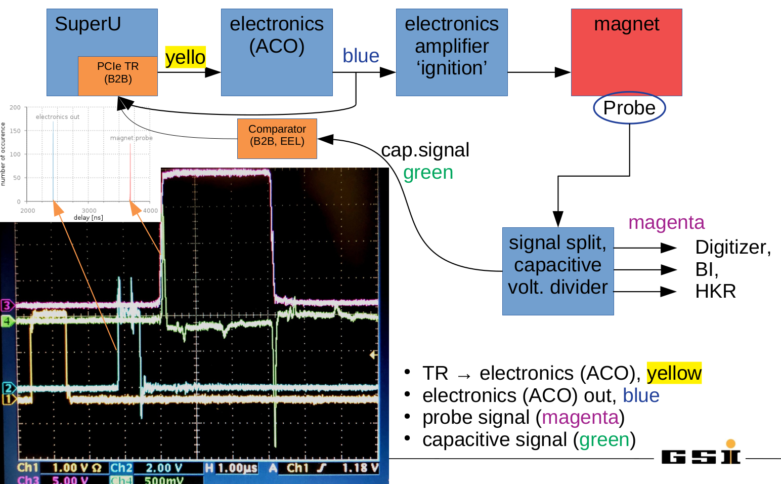
The following figure shows the relevant signals for triggering the kicker and signals used for diagnosics. Figure: Kicker signals and diagnostics. The figure on the oscilloscope screen show the following signals: Trigger from B2B (yellow), output from ACO electronics (blue), kicker magnet probe (magenta) and kicker magnet probe obtained via a capacitive voltage divider (green). Details see text.
The Bunch-2-Bucket system sends a timing message with CMD_B2B_TRIGGEREXT (not shown) to the Timing Receiver (TR) mounted in a 1U server. On-time, the TR creates a LVTTL signal (yellow) that is fed into a first set of electronics modules (this signal replaces the one from the famous 'Timing Generator'). The electronics performs certain tasks including the generation of a TTL signal (blue) that is fed into the main kicker electronics. When this happens, the kicker ignites and the kicker magnet is energized. A pickup probe allows to monitor the magnetic field at the kicker magnet. The probe signal is split and feeds various customers (magenta). The special feature of importance here is a capacitive voltage divider. A fast comparator is used to convert the output of the voltage divider signal to LVTTL (green). The bunch-2-bucket system uses the rising edges of signals for various purposes.
 - electronics out
- signal is active: confirmation the electronics is supplied with settings data and the kicker is active
- monitoring of the set-value of the delay that has been set for the kicker
- probe signal
- signal is active: indication, that the full kicker scenario is working
- monitoring of the real kick time
Data, Analysis and Discussion
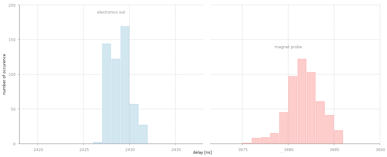
The B2B system acquires the timestamp of the rising edges of the 'electronic out' and 'magnet probe' signals. The intention is fast data acquisition, analysis and delivery of the data to the customer within 1ms after the kick. The purpose of the data is twofold: Firstly, they serve to monitor and diagnose the B2B and kicker systems. Second, the data is required, as an example, by our colleagues from beam instrumentation. However, the data acquired and distributed by the B2B are very basic and do not intend to compete with proper digitization of the analogue signals by other technical system at GSI/FAIR. Figure: Measured delays of the rising edges of the electronics out (blue) and kicker magnet (red) signals with respect to the trigger signal CMD_B2B_TRIGGEREXT. Please note, that the x-axis is not continuous and has nanosecond scale. For details see text.
Analysis
The figure above shows the observed timestamps [ns] of the electronics output signal and the kicker magnet probe signal. The data has been acquired in 520 extractions from SIS18 within ~2.5 hours of operation. In the analysis, the due-time of CMD_B2B_TRIGGEREXT has been subtracted from the data. Thus, each extraction provides two data points; the delay of the electronics output signals and the and delay of the beginning of the kick at the kicker magnet. Delays in (short) cables are not considered here. The data is then represented as histograms.
| what | kicker electronics | magnet probe |
|---|---|---|
| minimum [ns] | 2427 | 3675 |
| maximum [ns] | 2431 | 3685 |
| average [ns] | 2429.2 | 3681.2 |
| std dev [ns] | 1.08 | 1.86 |
| corr std dev [ns] | 1.02 | 1.82 |
| # of transfers | 520 | 520 |
- the probe signal is an analogue signal
- the amplitude changes if the kick angle in the ring is changed
- the comparator is operated at a fixed setting
- other customers are tapping the same probe signal
- they connect or disconnect at arbitrary times
- cables to the customers may be long; additional reflections do occur
- the signals from the capacitive divider are not a 50 Ohm system which may lead to strong additional reflections
- especially the so-called 'dumps' of the kicker system might cause additional electronic noise that is picked up. The dumps are 'fired' in less than 1 us before 'kicker ignition'. Especially when the kicker systems runs at high load, the pickup of electronic noise from the dumps can clearly be seen as a contribution to signals on an oscilloscope.
| I | Attachment | Action | Size | Date | Who | Comment |
|---|---|---|---|---|---|---|
| |
drNov2020_ESR18B2E.JPG | manage | 547 K | 2020-11-27 - 18:43 | UnknownUser | ESR - bunch to extraction |
| |
drNov2020_ESREKS.JPG | manage | 640 K | 2020-12-03 - 12:26 | UnknownUser | ESR: trigger kicker by event |
| |
drNov2020_SIS18EKS.JPG | manage | 602 K | 2020-12-03 - 12:21 | UnknownUser | SIS: trigger kicker by event |
| |
drNov2020_SIS18ESRB2C.JPG | manage | 669 K | 2020-11-27 - 18:48 | UnknownUser | SIS->ESR - bunch to coasting beam |
| |
drNov2020_noRF.JPG | manage | 1 MB | 2020-12-03 - 12:44 | UnknownUser | SIS: no RF signal from H=1 group DDS |
| |
kickerSISMonitorSignals.png | manage | 37 K | 2020-12-03 - 18:29 | UnknownUser | SIS: kicker monitor signals |
| |
kickerSignalsDiagnostic.png | manage | 640 K | 2020-12-03 - 17:59 | UnknownUser | SIS: kicker signals and diagnostic |
| |
kistTestNov2020_ESR.JPG | manage | 705 K | 2020-12-03 - 19:39 | UnknownUser | ESR: kicker monitor signals |
Edit | Attach | Print version | History: r6 < r5 < r4 < r3 | Backlinks | View wiki text | Edit wiki text | More topic actions
Topic revision: r6 - 2021-02-22, dbeck
 Copyright © by the contributing authors. All material on this collaboration platform is the property of the contributing authors.
 Ideas, requests, problems regarding GSI Wiki? Send feedback | Legal notice | Privacy Policy (german)


