You are here: GSI Wiki>TOS/BunchBucket Web>BunchBucketDocumentation>BunchBucketDocuments>BunchBucketTestsMeasurements>BunchBucketTestMeasurement15 (2023-11-06, dbeck)Edit Attach
November 2023: Testing Magnet Probe Signals at SIS18 Extraction
Table of ContentsTL;DR
Test on 3 November 2023. Seems to work.Introduction
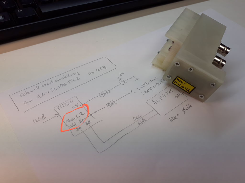
The b2b system uses timestamping with a White Rabbit timing receiver connected to the capacitive / differential signal of the kicker magnet to measure the time of the rising edge and possibly the length of the kicker flat-top. The main purpose is to provide this information to users in hard realtime: The data is sent via timing messages via the White Rabbit network and delivered (!) within less than 1 millisecond after the kick. Figure: Comparator hardware.
All software has been merged into the current 'fallout' branch, click.
Measurements
Testing the kicker was done at the following settings- pattern
SIS18_FAST_HHD_MD_BG - dry beam of element nitrogen 7+ gold @ 500 MeV / u
- at extraction: 1050 kHz revolution frequency, T_rev is 952 ns
- kicker deflection 4.85 mrad
- ParamModi value 'kick offset' 2.0 us
Comparator
The procedure has been the following.- set comparator level
- measure delay of probe signal at comparator output relative to CMD_B2B_TRIGGEREXT
- repeat this for different values of the comparator level
| comparator level [%] | delay rising edge [ns] | length output signal |
|---|---|---|
| 47 | n/a | n/a |
| 48 | n/a | n/a |
| 49 | n/a | n/a |
| 50 | 3346 | 3001 |
| 51 | 3352 | 2982 |
| 52 | 3359 | 2973 |
| 53 | 3361 | 1097 |
| 54 | 3366 | 962 |
| 55 | 3373 | 562 |
| 56 | 3372 | 507 |
| 57 | 3378 | 330 |
| 58 | 3382 | 233 |
| 59 | 3396 | 163 |
| 60 | 3405 | 90 |
| 61 | n/a | n/a |
| 62 | n/a | n/a |
| 62 | n/a | n/a |
Alignment with Digitizer Data
For better comparison with the digitizer data, the delay of the rising edge value of the digitizer signal (at 50%) relative to CMD_B2B_TRIGGEREXT has been determined a couple of times. The average value is a delay of 3307 ns. The calibration of a timestamp measurement with a White Rabbit timing receiver is not known to the nanosecond. However, this internal delay is estimated to about 29 ns.Data
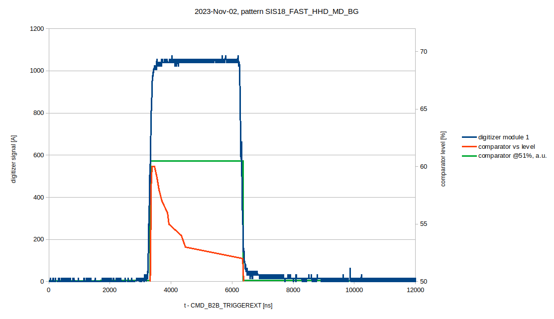
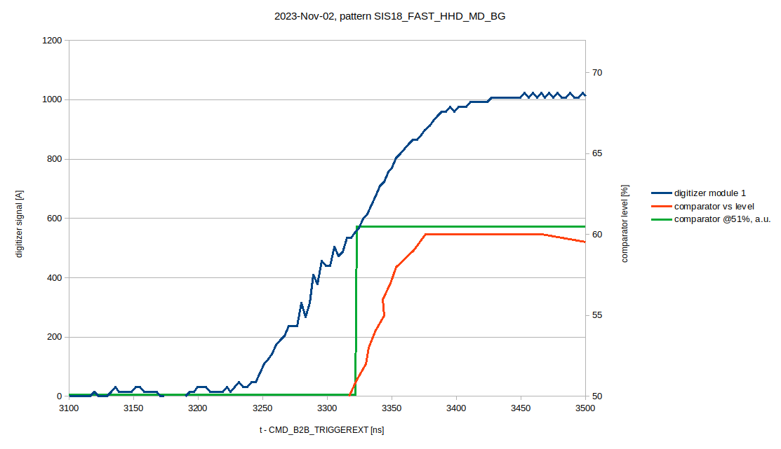
The data acquired using the comparator and the probe signal acquired by the digitizer connected to module 1 (GS04MK1E: Current_Module1:Triggered@312.5 MHz) are plotted.
 Figure: Signal of digitizer (blue) and data of the comparator level (red). Top: Complete signal. Bottom: Zoom at rising edge. The x-axis shows the delay after the trigger signal
 CMD_B2B_TRIGGEREXT. Left y-axis scale: Signal of digitizer [A]. Right y-axis scale: Comparator level [%]. The signal of comparator at a fixed level is shown in green. See text for details.
The above figures show three sets of data. - Shown in blue is the signal acquired by the digitizer (left y-axis).
- The red curve shows delays for rising and falling edge of the output signal delivered by the comparator for different levels (right y-axis); as can be seen, good comparator levels for matching the probe signal are within a range of 50..52%.
- The green curve (y-axis: arbitrary units) serves to compare the output signal of the comparator at a level of 51% to the digitizer values.
Conclusion
Today (November 2023) the rise time of the kicker magnet probe signal is measured and delivered to users in the entire facility. In 2023 a new comparator has been installed that allows to detect not only the rising but also the falling edge of the kicker signal. What remains to be done is the delivery of the falling edge timestamp. -- DietrichBeck - 02 Nov 2023| I | Attachment | Action | Size | Date | Who | Comment |
|---|---|---|---|---|---|---|
| |
2023-11-02_sis18-fast-hhd-module1-zoom.png | manage | 34 K | 2023-11-02 - 18:36 | UnknownUser | compararator vs digitizer, zoom to rising edge |
| |
2023-11-02_sis18-fast-hhd-module1.png | manage | 32 K | 2023-11-02 - 18:36 | UnknownUser | compararator vs digitizer, full signal |
| |
comparator-hardware.png | manage | 794 K | 2023-11-03 - 11:39 | UnknownUser | comparator hardware |
Edit | Attach | Print version | History: r5 < r4 < r3 < r2 | Backlinks | View wiki text | Edit wiki text | More topic actions
Topic revision: r5 - 2023-11-06, dbeck
 Copyright © by the contributing authors. All material on this collaboration platform is the property of the contributing authors.
 Ideas, requests, problems regarding GSI Wiki? Send feedback | Legal notice | Privacy Policy (german)


