You are here: GSI Wiki>EPS Web>AdaptiveControlUnit>NecessaryHardwareModifications>ICMPSSInterlock (2021-02-10, DerekSchupp)Edit Attach
ICM personal protection interlock (PSS)
Problem description:In order to be able to use the personal protection interlock on the ICM, a hardware modification is required.
The personal protection interlock signal is output via electrical output 3.
In the event of an interlock, there should be an active signal here.
Unfortunately, this is not possible because of a layout error, since in the event of an interlock the supply voltage of the optocoupler driving LED is switched off. Problem solution:
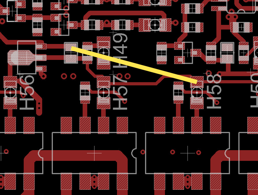
It is therefore necessary to use a solder bridge.
This connects JP20 (upper solder pad, permanent +5V) and the anode of H58.
H58 is to be installed vertically so that only the cathode remains connected to the circuit board of the ICM.

Edit | Attach | Print version | History: r2 < r1 | Backlinks | View wiki text | Edit wiki text | More topic actions
Topic revision: r2 - 2021-02-10, DerekSchupp
 Copyright © by the contributing authors. All material on this collaboration platform is the property of the contributing authors.
 Ideas, requests, problems regarding GSI Wiki? Send feedback | Legal notice | Privacy Policy (german)
