|
|
You are here: GSI Wiki>TOS/BunchBucket Web>BunchBucketDocumentation>BunchBucketDocuments>BunchBucketTestsMeasurements>BunchBucketTestMeasurement21 (2025-05-07, DietrichBeck)Edit Attach
May 2025: Phase Shift in the Integration System Using the OMU Prototype
Table of ContentsIntroduction
A prototype of the Optical Mixer Unit (OMU) was available in early May 2025. This was tested in the integration system.Setup
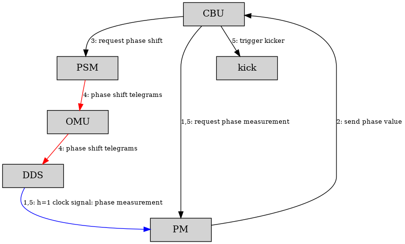
Figure: Schematic view of data flow. Boxes are hardware modules, each an FPGA connected to the White Rabbit network with a host system added: Central B2B Unit (CBU), Phase Shift Module (PSM), Optical Mixer Unit (OMU), Direct Digital Synthesis (DDS), Phase Measurement (PM) and Kicker Trigger (kick). Arrows indicate data flow. Black: timing messages sent via the White Rabbit network as broadcast. Red: phase shift telegrams via dedicated optical links. Blue: two different phase measurements of one clock output of the same DDS. Data flow for monitoring and diagnostic is not shown. The measurements were done to verify the combination of PSM, OMU, DDS and bunch-2-bucket system works as expected. In this prototype version, the message rate on the optical low-level-RF links is limited to 10 kHz (100 us interval). The message rate should be increased. However, the machine experiment is scheduled only three weeks from now on and it was decided not to change the setup. The data was acquired using the bunch-2-bucket system. Disclaimer: The bunch-2-bucket is not suited for this type of measurement as the high-precision measurement of the phase typically uses 30 samples of the h=1 DDS rising edge. With a h=1 period of 1.25 us this corresponds to a measurement time of about 37.5 us. Thus, the phase shifts happening at 100 us interval are expected to appear smeared out. The following settings were used.
- Pattern 'SCRATCH_HL_SIS18_FAST_HHD_20230130_104825.C1'
- SID 03
- bunch-2-bucket mode: fast extraction with preceding phase shift
- h=1 period: 1250.673 ns (~ 799.569 kHz)
- phase shift time: 5 ms and 0.5 ms
- phase shift value: 120 degree
Phase Shift at the SIS18
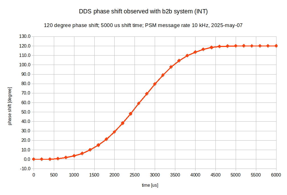 Figure: Phase shift of the h=1 DDS at SIS18 extraction as a function of time. Time for phase shift is 5 ms.
The figure above shows the phase shift of h=1 DDS prior extraction measured with the bunch-2-bucket system. As the low-level-RF system uses a message period of 100us, about 50 telegrams are used for the phase shift. The measured curve appears rather smooth.
Figure: Phase shift of the h=1 DDS at SIS18 extraction as a function of time. Time for phase shift is 5 ms.
The figure above shows the phase shift of h=1 DDS prior extraction measured with the bunch-2-bucket system. As the low-level-RF system uses a message period of 100us, about 50 telegrams are used for the phase shift. The measured curve appears rather smooth.
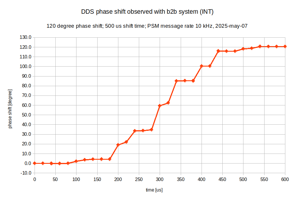 Figure: Phase shift of the h=1 DDS at SIS18 extraction as a function of time. Time for phase shift is 0.5 ms.
The figure above shows the phase shift of h=1 DDS but with a very short shift time of 0.5 ms only. As the low-level-RF system uses a message period of 100us, only ~5 telegrams are used for the phase shift.
One would expect a 'curve' with a step-function of five steps but the measured curve appears chaotic. At least two effects must be considered here.
Figure: Phase shift of the h=1 DDS at SIS18 extraction as a function of time. Time for phase shift is 0.5 ms.
The figure above shows the phase shift of h=1 DDS but with a very short shift time of 0.5 ms only. As the low-level-RF system uses a message period of 100us, only ~5 telegrams are used for the phase shift.
One would expect a 'curve' with a step-function of five steps but the measured curve appears chaotic. At least two effects must be considered here. - The bunch-2-bucket system is optimized for measuring the RF-phase precisely by employing the sub-nanoseconds-fit. With the parameters used here, such a measurement takes about 37.5 us. If the phase at the DDS is changed every 100 us, as phase measurement will sometimes be done at the transition between two steps and the transition between two steps can not be determined or is smeared out.
- Each data point of the figure above is an average of about 20 measurements. The PSM sends the messages at a fixed rate but not synchronized to White Rabbit or BuTiS. This leads to further smearing out when averaging over a longer time.
Summary
The system works as expected. The measured length and value of phase shifts match the set-values. For the measurement presented here, the message rate at which the phase-shift telegrams are sent is only 10 kHz. The curve acquired with a phase shift time of 5.0 ms looks smooth. As expected, the curve acquired with a shift time of only 0.5 ms shows a clear signature caused by the low message rate. However, this is not expected to cause issues with the beam transfer as- typical phase shift time is about 10 ms; this corresponds to about 100 telegrams
- the cavity synchronization has a control loop with ~100 us time constant; this will smear out the steps


| I | Attachment | Action | Size | Date | Who | Comment |
|---|---|---|---|---|---|---|
| |
2025-05-07_phase_shift_measurement_b2b-pshift-5000us-psm100us.png | manage | 42 K | 2025-05-07 - 13:42 | DietrichBeck | 5ms phase shift with 100us message rate |
| |
2025-05-07_phase_shift_measurement_b2b-pshift-500us-psm100us.png | manage | 42 K | 2025-05-07 - 13:56 | DietrichBeck | 0.5ms phase shift with 100us message rate |
Edit | Attach | Print version | History: r1 | Backlinks | View wiki text | Edit wiki text | More topic actions
Topic revision: r1 - 2025-05-07, DietrichBeck
Ideas, requests, problems regarding GSI Wiki? Send feedback | Legal notice | Privacy Policy (german)