
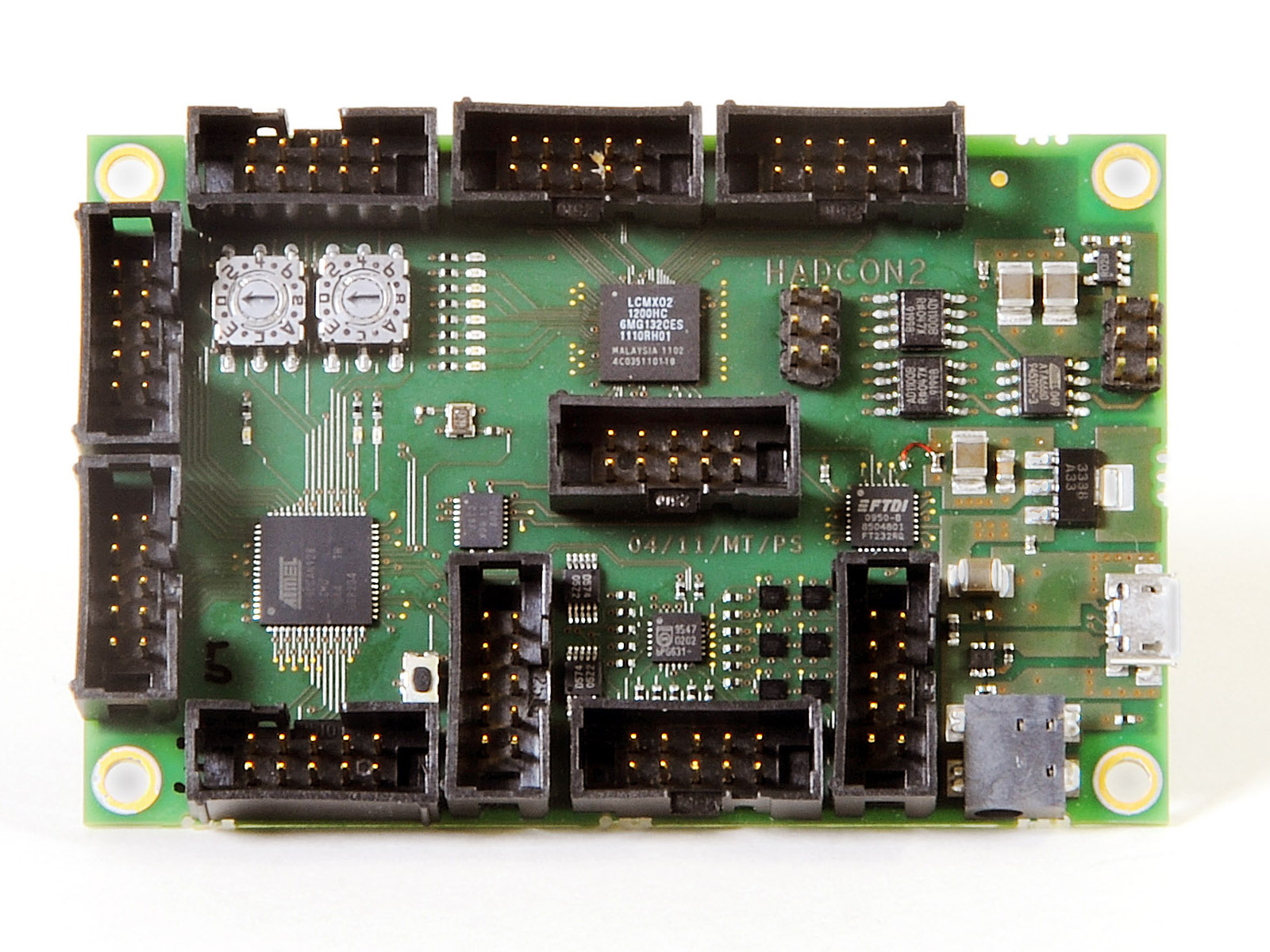
HadCon 2
HadCon2 is a credit-card sized general purpose I/O module for detector and experiment controls as well as for small data acquisition systems.
It is the successor of the discontinued first version
HadCon (
HADControl/HadShoPoMo general purpose board,
HadCon @ Epics Wiki).
The module has an ATMEL AT90CAN128 microcontroller providing a multitude of connectivity:
I2C (8/4 fold (intern/extern) multiplexer), 6 channel 1-wire master, 8-channel 8bit DAC, galvanically isolated CAN - high-speed transceiver, 8-channel 10-bit SAR ADC, byte-oriented SPI, in total up-to 53 programmable I/O lines and optionally a Lattice MachX02 FPGA for fast data processing tasks.
While the discontinued precursor HadCon had an SoC on-board, its successor HadCon2 has broken up this concept in favour of a more open access:
It doesn't have any CPU on board, but a USB connector to directly allow communication with any type and size of computer (e.g. PC, raspberry PI, dreamplug, ...) having an USB port on one side and at the other end the microcontroller and the FGPA. This communication is based on an ASCII-based protocol in view of easy implementation in detector control systems like e.g.
EPICS and LabVIEW.
- Summarizing:
- Microcontroller: ATMEL AT90CAN128
- FPGA: Lattice MachX02-1200-HC
- FTDI USB to serial UART interface
- USB 2.0 connector
- Power over USB
- I2C devices
- 6 × Single-Channel 1-Wire Master
- 1 × 8-channel I2C-bus multiplexer with reset
- 2 × 4-channel 8-Bit DAC - Digital-to-Analog Converter
- galvanically isolated CAN - High-speed CAN Transceiver
- optional external power supply
- 2 × Rotary Code Switches, hexadecimal coding
- Reset Button for ATMEL
- 11 × LED's, free programmable
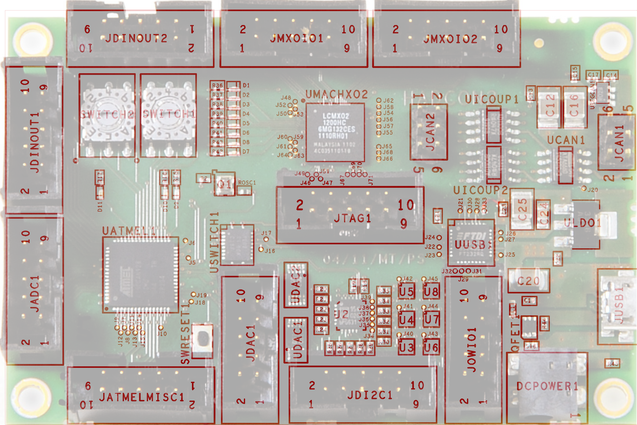
Layout
Microcontroller ATMEL
FPGA
FTDI USB to serial UART interface
USART - Universal Synchronous and Asynchronous serial Receiver and Transmitter
| |
connects to |
| USART0 |
FTDI (USB) |
| USART1 |
FPGA |
I2C
1 × 8-channel I2C-bus multiplexer with reset
-
 PCA9547, local copy
- ATMEL's SDA/SCLsignals are multiplexed to up-to 8 lines.
| | Multiplexer out | Device | Signals |
ATMEL's SDA/SCL | SD0/SC0 | DAC1: 4-channel DAC (DAC5574) | DACOUT1 ... DACOUT3 |
| DAC2: 4-channel DAC (DAC5574) | DACOUT4 ... DACOUT7 |
SD1/SC1, SDA1 / SCL1 | Connector JDI2C1 | |
SD2/SC2, SDA2 / SCL2 | |
SD3/SC3, SDA3 / SCL3 | |
SD4/SC4, SDA4 / SCL4 | |
SD5/SC5 | 2 × Single-Channel 1-Wire Master | OWIO0 ... OWIO1 |
SD6/SC6 | 2 × Single-Channel 1-Wire Master | OWIO2 ... OWIO3 |
SD7/SC7 | 2 × Single-Channel 1-Wire Master | OWIO4 ... OWIO5 |
- Addressing:
| Device | I2C sub address | Signals |
|---|
| A2 | A1 | A0 |
|---|
| U2: 8-channel I2C-bus multiplexer | 0 | 0 | 0 | OWIO0 |
- The configuration can be set via I2C.
- Connected to ATMEL's pin
PB5 (OC1A) [...] pulling the RESET pin LOW resets the I2C -bus state machine causing all the channels to be deselected, except Channel 0 so that the master can regain control of the bus (from the manual].
6 × Single-Channel 1-Wire Master
- I2C-to-1-Wire® bridge device DS2482-101, local copy
- Features:
- slew-rate control
- "To optimize 1-Wire waveform generation, the DS2482-101 performs slew-rate control on rising and falling 1-Wire edges and provides additional programmable features to match drive characteristics to the 1-Wire slave environment."
- pullup features
- "Programmable, strong pullup features support 1-Wire power delivery to 1-Wire devices such as EEPROMs and sensors."
- Addressing:
| Device |
I2C sub address |
Signals |
| A1 |
A0 |
| U3: Single-Channel 1-Wire Master |
1 |
0 |
OWIO0 |
| U6: Single-Channel 1-Wire Master |
1 |
1 |
OWIO1 |
| U4: Single-Channel 1-Wire Master |
1 |
0 |
OWIO2 |
| U7: Single-Channel 1-Wire Master |
1 |
1 |
OWIO3 |
| U5: Single-Channel 1-Wire Master |
1 |
0 |
OWIO4 |
| U8: Single-Channel 1-Wire Master |
1 |
1 |
OWIO5 |
2 × 4-channel 8-Bit DAC - Digital-to-Analog Converter
| Device |
I2C sub address |
Signals |
| A1 |
A0 |
| UDAC1: 4-channel DAC (DAC5574) |
1 |
0 |
DACOUT1 ... DACOUT3 |
| UDAC2: 4-channel DAC (DAC5574) |
0 |
0 |
DACOUT4 ... DACOUT7 |
galvanically isolated CAN-bus
Can - High-speed Can Transceiver
iCoupler Digital Isolator
8-bit noninverting translator
Switches
Rotary Code Switches, hexadecimal coding
| SWITCH1 |
Connector Pins |
AT90CAN128 via 4.7kΩ |
|
SWITCH2 |
Connector Pins |
AT90CAN128 via 4.7kΩ |
| 1 |
PC0 (A8) |
1 |
PC4 (A12) |
| 2 |
PC1 (A9) |
2 |
PC5 (A13) |
| 4 |
PC2 (A10) |
4 |
PC6 (A14) |
| 8 |
PC3 (A11) |
8 |
PC7 (A15/CLK0) |
- KMR223 ITT micro miniature switch
- pulls up ATMEL's
RESET (pin20) to 3.3V via 10kΩ
Power
Powering via
- micro USB
JUSB1 connector, or
- jack
DCPower
Output
| GND |
Can be found on several Connectors |
| 5,0V |
JCAN2 |
pin 4 |
| 3,3V |
JCAN2 |
pin 6 |
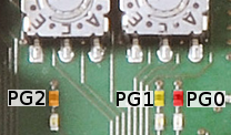
LEDs
| |
pin |
color |
logic |
| AT90CAN128 |
PG0 ( WR ) |
♦ red |
inverse logic:
0: on 1: off |
PG1 ( RD ) |
♦ yellow |
PG2 (ALE) |
♦ orange |
| MachX02 |
PT17D "DONE" |
♦ red |
|
PL4A |
♦ yellow |
|
PL4B |
♦ orange |
|
PL4C |
♦ yellow |
|
PL4D |
♦ orange |
|
PL5A |
♦ red |
|
PL5B |
♦ yellow |
|
PL5C |
♦ orange |
|
Connectors
JDINOUT1 / JDINOUT2
| JDINOUT1 |
Connector Pins |
AT90CAN128 |
|
JDINOUT2 |
Connector Pins |
AT90CAN128 |
| 1 |
PA0 (AD0) |
1 |
PC0 (A8) |
| 2 |
PA1 (AD1) |
2 |
PC1 (A9) |
| 3 |
PA2 (AD2) |
3 |
PC2 (A10) |
| 4 |
PA3 (AD3) |
4 |
PC3 (A11) |
| 5 |
PA4 (AD4) |
5 |
PC4 (A12) |
| 6 |
PA5 (AD5) |
6 |
PC5 (A13) |
| 7 |
PA6 (AD6) |
7 |
PC6 (A14) |
| 8 |
PA7 (AD7) |
8 |
PC7 (A15/CLK0) |
| 9/10 |
GND |
9/10 |
GND |
JADC1
| Connector Pins |
AT90CAN128 |
comments |
| 1 |
PF0 (ADC0) |
|
| 2 |
PF1 (ADC1) |
| 3 |
PF2 (ADC2) |
| 4 |
PF3 (ADC3) |
|
| 5 |
PF4 (ADC4) |
overlap with JTAG inputs of ATMEL, can be decoupled by pulling TOSC2 low |
| 6 |
PF5 (ADC5) |
| 7 |
PF6 (ADC6) |
| 8 |
PF7 (ADC7) |
|
| 9/10 |
GND |
JAtmelMISC1
- ATMEL miscellaneous I/O, SPI
| Connector Pins |
AT90CAN128 |
comments |
| 1 |
PD2 (RXD1/INT2) |
USART1 RXD to connection to MachX02 or External Interrupt 2 Input |
| 2 |
PD1 (TXD1/INT3) |
USART1 TXD to connection to MachX02 or External Interrupt 3 Input |
| 3 |
PB0 ( SS ) |
Serial Peripheral Interface – SPI |
| 4 |
PB1 (SCK) |
| 5 |
PB2 (MOSI) |
| 6 |
PB3 (MISO) |
| 7 |
PE6 (T3/INT6) |
Timer/Counter3 Clock Input or External Interrupt 6 Input |
| 8 |
PE7 (ICP3/INT7) |
Timer/Counter3 Input Capture Trigger or External Interrupt 7 Input |
|
| 9/10 |
GND |
JTAG1
| Connector Pins |
Signal |
comments |
| 1 |
TCK |
10kΩ to V3_3 |
| 2 |
GND |
|
| 3 |
TDO |
← FPGA / Jumper J1 ← ATMEL |
| 4 |
V3_3 |
|
| 5 |
TMS |
|
| 6 |
|
not connected |
| 7 |
V3_3 |
|
| 8 |
|
not connected |
| 9 |
TDI |
→ ATMEL (→ FPGA) |
| 10 |
GND |
|
JCAN1 / JCAN2
- JCAN1 basic CAN connector
| JCAN1 |
Connector Pins |
Signal |
comments |
| 1 |
CANL |
↔ CAN - High-speed Can Transceiver ATA6660 ↔ iCoupler Digital Isolator ↔ ATMEL |
| 2 |
CANH |
| 3/5 |
VCAN_INPUT |
| 4/6 |
GND_CAN |
-
JCAN2 provides optional CAN power supply,
needs a jumper/cable/connection
- between pin
1, GND_CAN and pins 3/5 for common GND
- between pin
2, VCAN and pins 4 for 5,0V or
- between pin
2, VCAN and pins 6 for 3,3V
| JCAN2 |
Connector Pins |
Signal |
| 1 |
GND_CAN |
| 2 |
VCAN |
| 4 |
V5_0 |
| 6 |
V3_3 |
| 3/5 |
GND_CAN |
JMXOIO1 / JMXOIO2
| JMXOIO1 |
Connector Pins |
MachX02 |
|
JMXOIO2 |
Connector Pins |
MachX02 |
| 1/2 |
PT9A/B |
1/2 |
PT15A/B |
| 3/4 |
PT10A/B |
3/4 |
PT16A/B |
| 5/6 |
PT11A/B |
5/6 |
PT16C/D |
| 7/8 |
PT12A/B |
7/8 |
PT17A/B |
| 9/10 |
GND |
9/10 |
GND |
JDI2C1
- 4 of 8 channel output of ATMEL's single I2C bus multiplexed by an 8-channel I2C multiplexer PCA9547 (q.v. above)
JDAC1
- Output of the 2 4-channel DAC (DAC5574)
| Connector Pins |
Signal |
Device |
Device pin |
| 1 |
DACOUT0 |
UDAC1 |
VoutA |
| 2 |
DACOUT1 |
VoutB |
| 3 |
DACOUT2 |
VoutC |
| 4 |
DACOUT3 |
VoutD |
| 5 |
DACOUT4 |
UDAC2 |
VoutA |
| 6 |
DACOUT5 |
VoutB |
| 7 |
DACOUT6 |
VoutC |
| 8 |
DACOUT7 |
VoutD |
| 9/10 |
GND |
JOWIO1
- 1-wire connector for 6 channels provided by the 6 I2C driven Single-Channel 1-Wire Master DS2482
Notes and Remarks
1-wire
- When driving 1-wire devices, typically via
JOWIO1, make sure to have (at least) 1 pull-up resistor of about 3.3kΩ on the data line of the 1-wire bus connected to the power VDD.
- Recommended to have it at the master, e.g. at HadCon 's connector
JOWIO1,.
- Possible option for future, directly at the connector, when using one of JDINOUT2'spins as permanent power pin.
- Since Single-Channel 1-Wire Master DS2482 is used at
JOWIO1, this isn't necessary anymore, but keep in mind for other applications.
Tweaks / Bugfix
- template 1
- description
Therefore Action: i.e.
- pin 5 of
UFF2 has to be disconnected from its pad and removed
- A cable has to be soldered connecting pin 1 of
UFF2 to the solder pad of pin 5
- template 2
- description
Therefore Action: i.e.
- pin 5 of
UFF2 has to be disconnected from its pad and removed
- A cable has to be soldered connecting pin 1 of
UFF2 to the solder pad of pin 5
Firmware
Microcontroller Code
FPGA Code
Cables
Bookkeeping / Organization
--
PeterZumbruch - 2020-07-31
 :
: