
HadCon 2 - Documentation
Documentation
Technical Documentation of
HadCon2 and its components
- Summarizing:
- Microcontroller: ATMEL AT90CAN128
- FPGA: Lattice MachX02-1200-HC
- FTDI USB to serial UART interface
- USB 2.0 connector
- Power over USB
- I2C devices
- 6 × Single-Channel 1-Wire Master
- 1 × 8-channel I2C-bus multiplexer with reset
- 2 × 4-channel 8-Bit DAC - Digital-to-Analog Converter
- galvanically isolated CAN - High-speed CAN Transceiver
- optional external power supply
- 2 × Rotary Code Switches, hexadecimal coding
- Reset Button for ATMEL
- 11 × LED's, free programmable
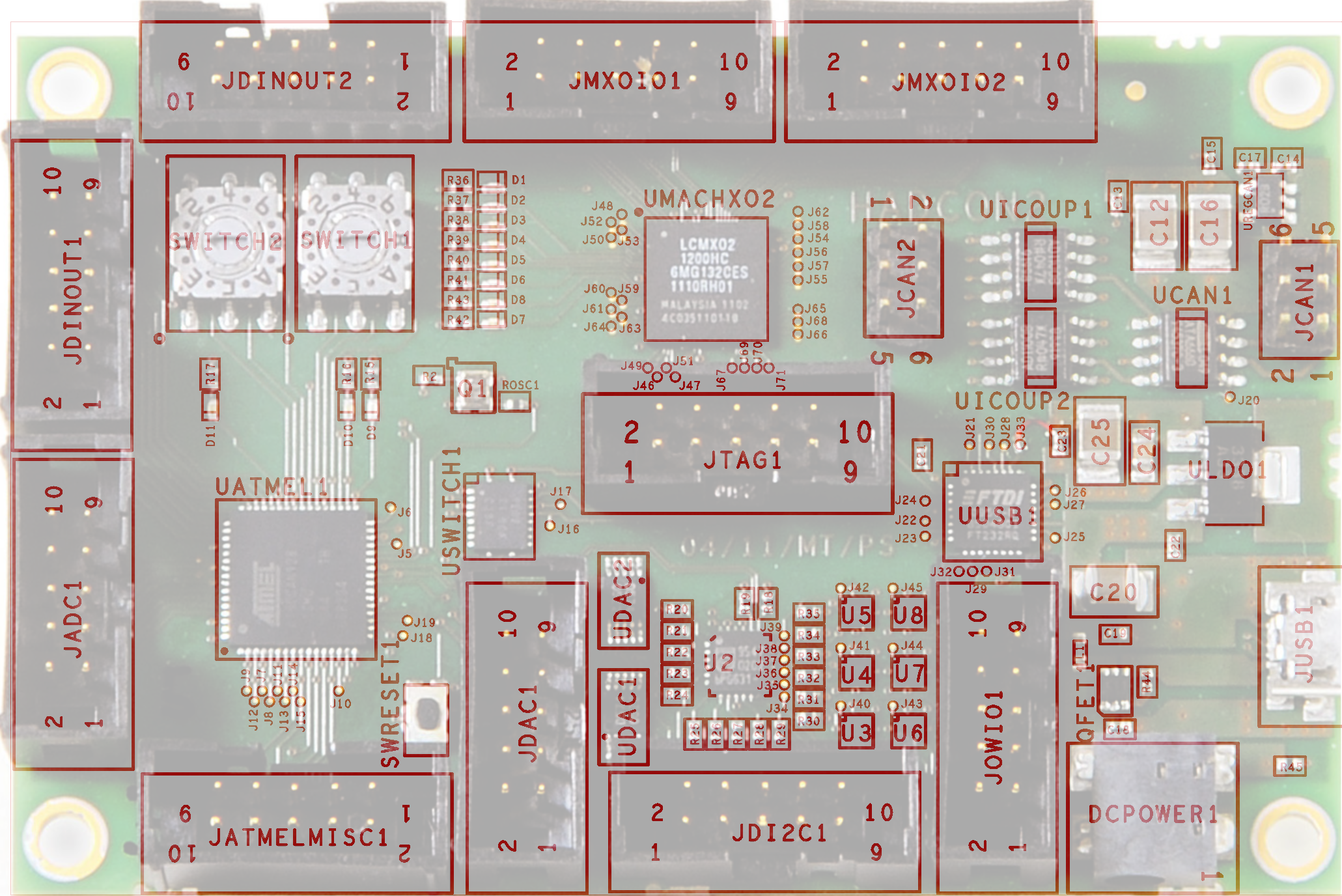
Layout
Microcontroller ATMEL
FPGA
FTDI USB to serial UART interface
USART - Universal Synchronous and Asynchronous serial Receiver and Transmitter
| |
connects to |
| USART0 |
FTDI (USB) |
| USART1 |
FPGA |
I2C
1 × 8-channel I2C-bus multiplexer with reset
-
 PCA9547, local copy
- ATMEL's SDA/SCLsignals are multiplexed to up-to 8 lines.
| | Multiplexer out | Device | Signals |
ATMEL's SDA/SCL | SD0/SC0 | DAC1: 4-channel DAC (DAC5574) | DACOUT1 ... DACOUT3 |
| DAC2: 4-channel DAC (DAC5574) | DACOUT4 ... DACOUT7 |
SD1/SC1, SDA1 / SCL1 | Connector JDI2C1 | |
SD2/SC2, SDA2 / SCL2 | |
SD3/SC3, SDA3 / SCL3 | |
SD4/SC4, SDA4 / SCL4 | |
SD5/SC5 | 2 × Single-Channel 1-Wire Master | OWIO0 ... OWIO1 |
SD6/SC6 | 2 × Single-Channel 1-Wire Master | OWIO2 ... OWIO3 |
SD7/SC7 | 2 × Single-Channel 1-Wire Master | OWIO4 ... OWIO5 |
- Addressing:
| Device | I2C sub address | Signals |
|---|
| A2 | A1 | A0 |
|---|
| U2: 8-channel I2C-bus multiplexer | 0 | 0 | 0 | OWIO0 |
- The configuration can be set via I2C.
- Connected to ATMEL's pin
PB5 (OC1A) [...] pulling the RESET pin LOW resets the I2C -bus state machine causing all the channels to be deselected, except Channel 0 so that the master can regain control of the bus (from the manual].
6 × Single-Channel 1-Wire Master
- I2C-to-1-Wire® bridge device DS2482-101, local copy
- Features:
- slew-rate control
- "To optimize 1-Wire waveform generation, the DS2482-101 performs slew-rate control on rising and falling 1-Wire edges and provides additional programmable features to match drive characteristics to the 1-Wire slave environment."
- pullup features
- "Programmable, strong pullup features support 1-Wire power delivery to 1-Wire devices such as EEPROMs and sensors."
- Addressing:
| Device |
I2C sub address |
Signals |
| A1 |
A0 |
| U3: Single-Channel 1-Wire Master |
1 |
0 |
OWIO0 |
| U6: Single-Channel 1-Wire Master |
1 |
1 |
OWIO1 |
| U4: Single-Channel 1-Wire Master |
1 |
0 |
OWIO2 |
| U7: Single-Channel 1-Wire Master |
1 |
1 |
OWIO3 |
| U5: Single-Channel 1-Wire Master |
1 |
0 |
OWIO4 |
| U8: Single-Channel 1-Wire Master |
1 |
1 |
OWIO5 |
2 × 4-channel 8-Bit DAC - Digital-to-Analog Converter
| Device |
I2C sub address |
Signals |
| A1 |
A0 |
| UDAC1: 4-channel DAC (DAC5574) |
1 |
0 |
DACOUT1 ... DACOUT3 |
| UDAC2: 4-channel DAC (DAC5574) |
0 |
0 |
DACOUT4 ... DACOUT7 |
galvanically isolated CAN-bus
Can - High-speed Can Transceiver
iCoupler Digital Isolator
8-bit noninverting translator
Switches
Rotary Code Switches, hexadecimal coding
| SWITCH1 |
Connector Pins |
AT90CAN128 via 4.7kΩ |
|
SWITCH2 |
Connector Pins |
AT90CAN128 via 4.7kΩ |
| 1 |
PC0 (A8) |
1 |
PC4 (A12) |
| 2 |
PC1 (A9) |
2 |
PC5 (A13) |
| 4 |
PC2 (A10) |
4 |
PC6 (A14) |
| 8 |
PC3 (A11) |
8 |
PC7 (A15/CLK0) |
- KMR223 ITT micro miniature switch
- pulls up ATMEL's
RESET (pin20) to 3.3V via 10kΩ
Power
Powering via
- micro USB
JUSB1 connector, or
- jack
DCPower
Output
| GND |
Can be found on several Connectors |
| 5,0V |
JCAN2 |
pin 4 |
| 3,3V |
JCAN2 |
pin 6 |
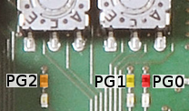
LEDs
| |
pin |
color |
logic |
| AT90CAN128 |
PG0 ( WR ) |
♦ red |
inverse logic:
0: on 1: off |
PG1 ( RD ) |
♦ yellow |
PG2 (ALE) |
♦ orange |
| MachX02 |
PT17D "DONE" |
♦ red |
|
PL4A |
♦ yellow |
|
PL4B |
♦ orange |
|
PL4C |
♦ yellow |
|
PL4D |
♦ orange |
|
PL5A |
♦ red |
|
PL5B |
♦ yellow |
|
PL5C |
♦ orange |
|
Connectors
JDINOUT1 / JDINOUT2
| JDINOUT1 |
Connector Pins |
AT90CAN128 |
|
JDINOUT2 |
Connector Pins |
AT90CAN128 |
| 1 |
PA0 (AD0) |
1 |
PC0 (A8) |
| 2 |
PA1 (AD1) |
2 |
PC1 (A9) |
| 3 |
PA2 (AD2) |
3 |
PC2 (A10) |
| 4 |
PA3 (AD3) |
4 |
PC3 (A11) |
| 5 |
PA4 (AD4) |
5 |
PC4 (A12) |
| 6 |
PA5 (AD5) |
6 |
PC5 (A13) |
| 7 |
PA6 (AD6) |
7 |
PC6 (A14) |
| 8 |
PA7 (AD7) |
8 |
PC7 (A15/CLK0) |
| 9/10 |
GND |
9/10 |
GND |
JADC1
| Connector Pins |
AT90CAN128 |
comments |
| 1 |
PF0 (ADC0) |
|
| 2 |
PF1 (ADC1) |
| 3 |
PF2 (ADC2) |
| 4 |
PF3 (ADC3) |
|
| 5 |
PF4 (ADC4) |
overlap with JTAG inputs of ATMEL, can be decoupled by pulling TOSC2 low |
| 6 |
PF5 (ADC5) |
| 7 |
PF6 (ADC6) |
| 8 |
PF7 (ADC7) |
|
| 9/10 |
GND |
JAtmelMISC1
- ATMEL miscellaneous I/O, SPI
| Connector Pins |
AT90CAN128 |
comments |
| 1 |
PD2 (RXD1/INT2) |
USART1 RXD to connection to MachX02 or External Interrupt 2 Input |
| 2 |
PD1 (TXD1/INT3) |
USART1 TXD to connection to MachX02 or External Interrupt 3 Input |
| 3 |
PB0 ( SS ) |
Serial Peripheral Interface – SPI |
| 4 |
PB1 (SCK) |
| 5 |
PB2 (MOSI) |
| 6 |
PB3 (MISO) |
| 7 |
PE6 (T3/INT6) |
Timer/Counter3 Clock Input or External Interrupt 6 Input |
| 8 |
PE7 (ICP3/INT7) |
Timer/Counter3 Input Capture Trigger or External Interrupt 7 Input |
|
| 9/10 |
GND |
JTAG1
| Connector Pins |
Signal |
comments |
| 1 |
TCK |
10kΩ to V3_3 |
| 2 |
GND |
|
| 3 |
TDO |
← FPGA / Jumper J1 ← ATMEL |
| 4 |
V3_3 |
|
| 5 |
TMS |
|
| 6 |
|
not connected |
| 7 |
V3_3 |
|
| 8 |
|
not connected |
| 9 |
TDI |
→ ATMEL (→ FPGA) |
| 10 |
GND |
|
JCAN1 / JCAN2
- JCAN1 basic CAN connector
| JCAN1 |
Connector Pins |
Signal |
comments |
| 1 |
CANL |
↔ CAN - High-speed Can Transceiver ATA6660 ↔ iCoupler Digital Isolator ↔ ATMEL |
| 2 |
CANH |
| 3/5 |
VCAN_INPUT |
| 4/6 |
GND_CAN |
-
JCAN2 provides optional CAN power supply,
needs a jumper/cable/connection
- between pin
1, GND_CAN and pins 3/5 for common GND
- between pin
2, VCAN and pins 4 for 5,0V or
- between pin
2, VCAN and pins 6 for 3,3V
| JCAN2 |
Connector Pins |
Signal |
| 1 |
GND_CAN |
| 2 |
VCAN |
| 4 |
V5_0 |
| 6 |
V3_3 |
| 3/5 |
GND_CAN |
JMXOIO1 / JMXOIO2
| JMXOIO1 |
Connector Pins |
MachX02 |
|
JMXOIO2 |
Connector Pins |
MachX02 |
| 1/2 |
PT9A/B |
1/2 |
PT15A/B |
| 3/4 |
PT10A/B |
3/4 |
PT16A/B |
| 5/6 |
PT11A/B |
5/6 |
PT16C/D |
| 7/8 |
PT12A/B |
7/8 |
PT17A/B |
| 9/10 |
GND |
9/10 |
GND |
JDI2C1
- 4 of 8 channel output of ATMEL's single I2C bus multiplexed by an 8-channel I2C multiplexer PCA9547 (q.v. above)
JDAC1
- Output of the 2 4-channel DAC (DAC5574)
| Connector Pins |
Signal |
Device |
Device pin |
| 1 |
DACOUT0 |
UDAC1 |
VoutA |
| 2 |
DACOUT1 |
VoutB |
| 3 |
DACOUT2 |
VoutC |
| 4 |
DACOUT3 |
VoutD |
| 5 |
DACOUT4 |
UDAC2 |
VoutA |
| 6 |
DACOUT5 |
VoutB |
| 7 |
DACOUT6 |
VoutC |
| 8 |
DACOUT7 |
VoutD |
| 9/10 |
GND |
JOWIO1
- 1-wire connector for 6 channels provided by the 6 I2C driven Single-Channel 1-Wire Master DS2482
Notes and Remarks
1-wire
- When driving 1-wire devices, typically via
JOWIO1, make sure to have (at least) 1 pull-up resistor of about 3.3kΩ on the data line of the 1-wire bus connected to the power VDD.
- Recommended to have it at the master, e.g. at HadCon 's connector
JOWIO1,.
- Possible option for future, directly at the connector, when using one of JDINOUT2'spins as permanent power pin.
- Since Single-Channel 1-Wire Master DS2482 is used at
JOWIO1, this isn't necessary anymore, but keep in mind for other applications.
Tweaks / Bugfix
- template 1
- description
Therefore Action: i.e.
- pin 5 of
UFF2 has to be disconnected from its pad and removed
- A cable has to be soldered connecting pin 1 of
UFF2 to the solder pad of pin 5
- template 2
- description
Therefore Action: i.e.
- pin 5 of
UFF2 has to be disconnected from its pad and removed
- A cable has to be soldered connecting pin 1 of
UFF2 to the solder pad of pin 5
--
PeterZumbruch - 2020-11-09
 :
: