April 2025: Phase Shift in the Production System
Table of ContentsIntroduction
The beam time 2025 had a short break around Easter from 9..21 April. This slot was used to deploy updates required for phase shifting to the production system.- bunch-2-bucket firmware and software for all three ring machines
- new phase shift modules; these are hardware modules of the low-level rf-system installed at SIS18 and ESR
- prototypes of the OMU; these are hardware modules taking care of shifting DDS systems of different harmonicas simultaneously and synchronized
Setup
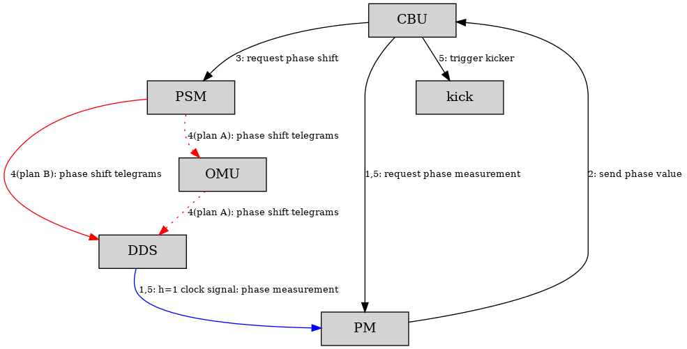
Figure: Schematic view of data flow. Boxes are hardware modules, each an FPGA connected to the White Rabbit network with a host system added: Central B2B Unit (CBU), Phase Shift Module (PSM), Optical Mixer Unit (OMU), Direct Digital Synthesis (DDS), Phase Measurement (PM) and Kicker Trigger (kick). Arrows indicate data flow. Black: timing messages sent via the White Rabbit network as broadcast. Red: phase shift telegrams via dedicated optical link. Blue: two different phase measurements of one clock output of the same DDS. Data flow for monitoring and diagnostic is not shown. As the main difference to the setup in the integration system the OMU was added. The OMU takes care of multiplying the phase shift telegrams for the DDS system of different harmonics. As an example, shifting h=1 by 90 degree requires shifting h=2 by 180 degree. The OMU has distinct outputs for different harmonics. However, using the OMU did not work at this time. A follow-up analysis identified a problem in the communication between PSM and OMU. As a consequence, this test was done without OMU but via a direct link between PSM und DDS. Thus, only the h=1 DDS was shifted, see 'Plan B' in the figure above. The data was acquired using an oscilloscope. The following settings were used.
- Pattern 'SIS18_SL_ESR_4CRYRING_COPY_21March25'
- SID 07
- bunch-2-bucket mode: fast extraction with preceding phase shift
- h=1 period: 2109.985 ns (~ 474 kHz)
- phase shift time: 5 ms
- phase shift value: 90 degree
Phase Shift at the SIS18
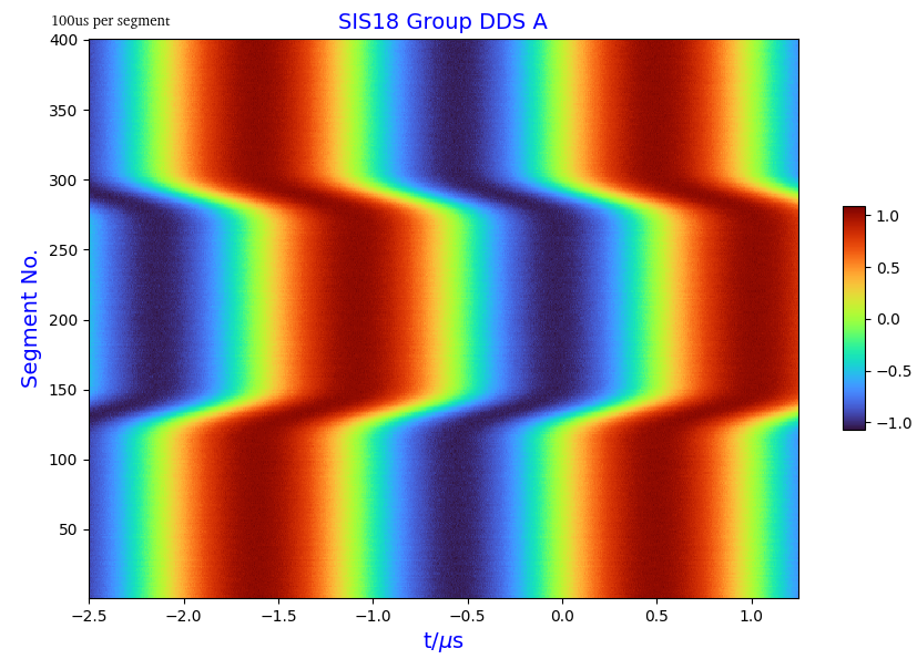 Figure: Relative phase between two DDS systems (h=1). Waterfall plot taken with oscilloscope. x-axis: relative phase between the two DDS systems. y-axis: time: one segment equals 100 us.
The figure above shows a waterfall plot of the phase difference between two DDS systems. Shown is the development of the relative phase (x-axis) with time (y-axis). The plot shows two signals, as the x-axis covers a range of almost 4 us, which is about two times the h=1 period. The scale on the y-axis is given in segments. With 400 segments of 100 us each, the plot shows the development of the phase over 40 ms.
Figure: Relative phase between two DDS systems (h=1). Waterfall plot taken with oscilloscope. x-axis: relative phase between the two DDS systems. y-axis: time: one segment equals 100 us.
The figure above shows a waterfall plot of the phase difference between two DDS systems. Shown is the development of the relative phase (x-axis) with time (y-axis). The plot shows two signals, as the x-axis covers a range of almost 4 us, which is about two times the h=1 period. The scale on the y-axis is given in segments. With 400 segments of 100 us each, the plot shows the development of the phase over 40 ms.
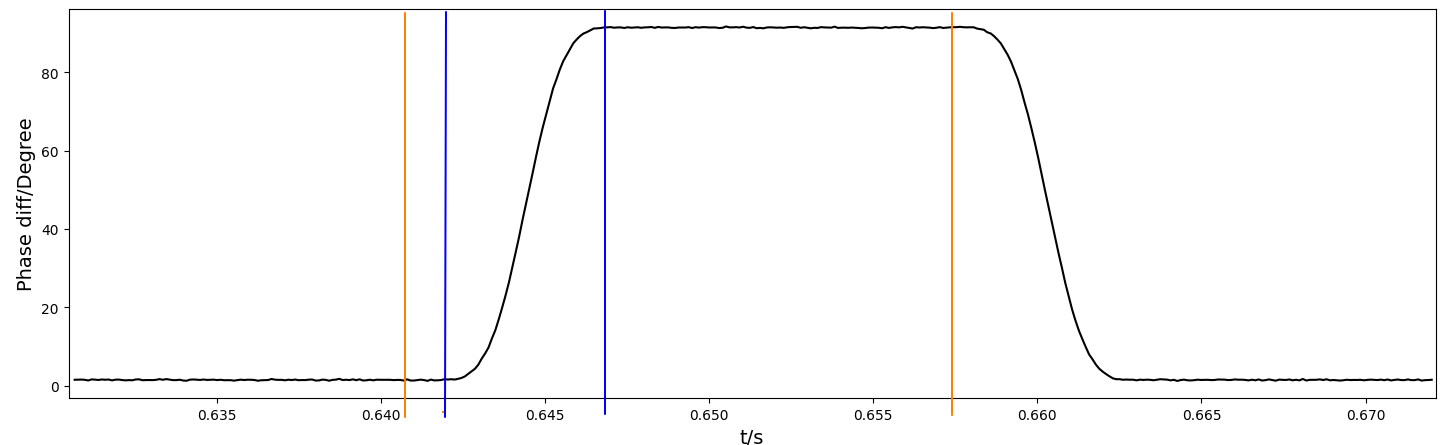 Figure: Relative phase between two DDS systems (h=1, one shifted, one un-shifted) with fast extraction at SIS18. Blue lines indicate the time windows for shifting (here: 5ms). Orange lines indicate the extraction flattop.
The figure above gives analysis of the waterfall plot. Shown is the relative phase as a function of time. The system behaves as expected:
Figure: Relative phase between two DDS systems (h=1, one shifted, one un-shifted) with fast extraction at SIS18. Blue lines indicate the time windows for shifting (here: 5ms). Orange lines indicate the extraction flattop.
The figure above gives analysis of the waterfall plot. Shown is the relative phase as a function of time. The system behaves as expected: - start of phase shift at 1.5 ms after begin of flat top
- phase shift time is 5.0 ms
- phase shift value is 90 degree
- phase is shifted back to original value after the end of the flat top.


| I | Attachment | Action | Size | Date | Who | Comment |
|---|---|---|---|---|---|---|
| |
2025-04-10_b2b-pro_phase-shift-sis18_dds-phase-comparison.png | manage | 34 K | 2025-04-28 - 09:17 | DietrichBeck | phase shift |
| |
2025-04-10_b2b-pro_phase-shift-sis18_waterfall-segment100us.png | manage | 411 K | 2025-04-28 - 09:17 | DietrichBeck | waterfall |
This topic: TOS/BunchBucket > WebHome > BunchBucketDocumentation > BunchBucketDocuments > BunchBucketTestsMeasurements > BunchBucketTestMeasurement19
Topic revision: 2025-04-28, DietrichBeck
Topic revision: 2025-04-28, DietrichBeck
Ideas, requests, problems regarding GSI Wiki? Send feedback | Legal notice | Privacy Policy (german)