April 2025: Bunch-2-Bucket SIS18 -> ESR with Phaseshift
Table of ContentsIntroduction
The beam time 2025 had a short break around Easter from 9..21 April. This slot was used to deploy updates required for phase shifting to the production system.- bunch-2-bucket firmware and software for all three ring machines
- new phase shift modules; these are hardware modules of the low-level rf-system installed at SIS18 and ESR
- prototypes of the OMU; these are hardware modules taking care of shifting DDS systems of different harmonicas simultaneously and synchronized
Setup
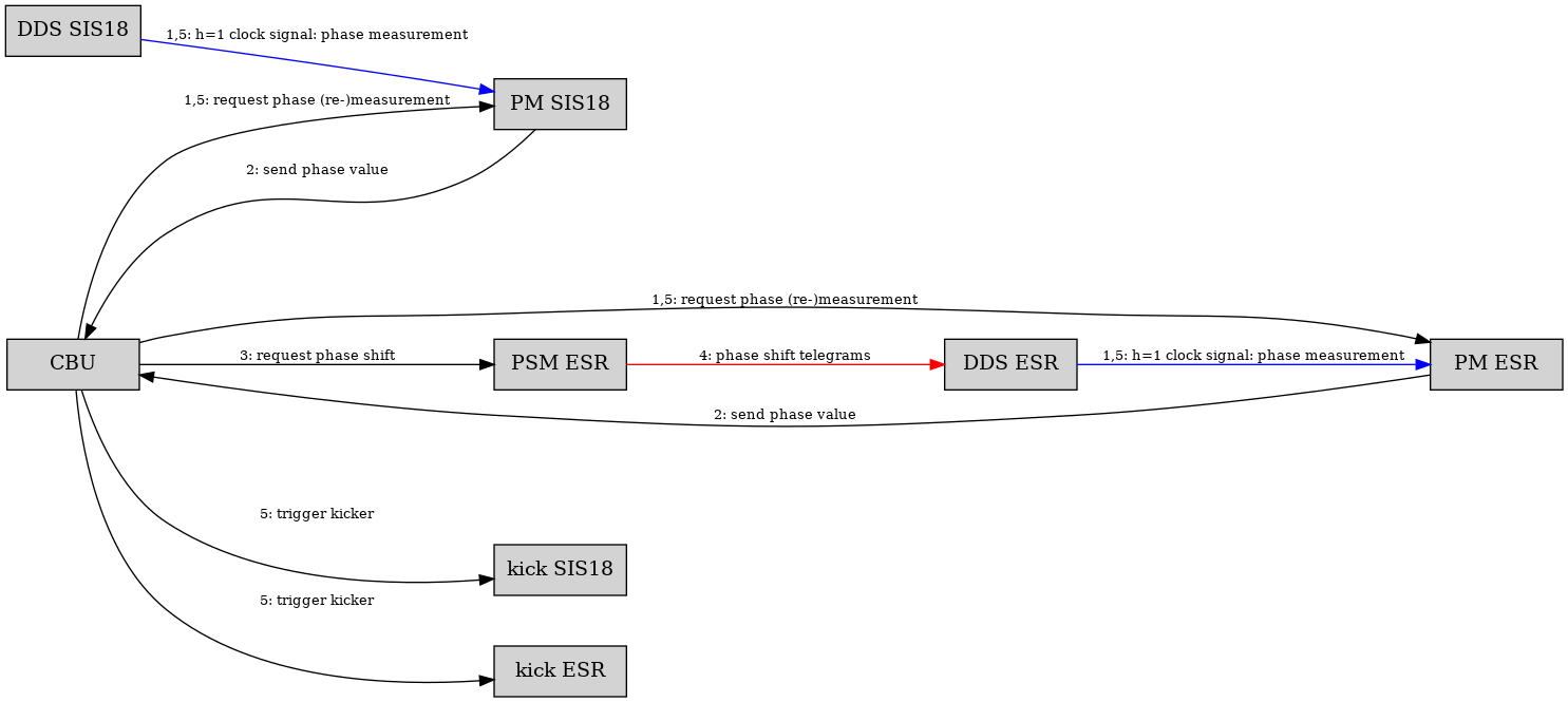
Figure: Figure: Schematic view of data flow. Boxes are hardware modules, each an FPGA connected to the White Rabbit network with a host system added: Central B2B Unit (CBU), Phase Shift Module (PSM), Direct Digital Synthesis (DDS), Phase Measurement (PM) and Kicker Trigger (kick). Arrows indicate data flow. Black: timing messages sent via the White Rabbit network as broadcast. Red: phase shift telegrams via dedicated optical link. Blue: two different phase measurements of one clock output of the same DDS. Data flow for monitoring and diagnostic is not shown. The setup is shown above. It is very similar to the one done earlier (click. As the main difference, the phase of not only one but two ring machines is measured. Moreover, the kickers of two ring machines are triggered. The procedure is the following
- the CBU defines the time
T_transferat which the transfer should happen - the CBU requests a phase measurement at both ring machines (1)
- when the results are received (2) the CBU calculated the phase difference of the two DDS systems in both ring machines
- the phase difference is the value by which one DDS system has to be shifted; here, the phase was shifted at the injection ring (ESR)
- the CBU requests the phase shift at the injection ring (3)
- the PSM performs the phase shift (4)
- the CBU requests kicker triggers at
T_transfer(5) - (the kickers will be triggered at
T_transfer) - the request for the kicker trigger also initiates a phase re-measurement at the PM systems of both rings (5)
- the measured phase difference should match the requested value; the measured value is recorded
- SIS18
- pattern: SIS18_SL_ESR_4CRYRING_COPY_21March25
- SID 07
- bunch-2-bucket mode: bunch-2-bucket, phase shift at injection ring
- h=1 period: 2109.985 ns (~ 474 kHz)
- phase shift time: 10 ms
- phase shift value: determined on-the-fly
- setting for 197Au @ 60 MeV/u
- ESR
- pattern: ESR_HITRAP_DUMMY_v2
- SID 07
- h=1 period: 4943.406 ns (~ 202 kHz)
- setting for 197Au @ 2.5 MeV/u
Bunch-2-Bucket Transfer
The extraction energy at SIS18 an injection energy at ESR did not match at all. Thus, this is a just a technical test to achieve phase matching of both rf-systems of both rings under unfavorable conditions.Frequency Beating
This is not expected to work but we tried anyhow.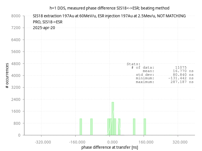 Figure: Histogram: Number of occurrences vs DDS phase difference of both rings at transfer. Details see text.
The figure shows a histogram where the number of occurrences is plotted vs the DDS phase difference between both ring machines at transfer. As expected, the phase matching between both ring is lousy with differences up to 8% of the the revolution time of SIS18 (+/- ~30 degree).
This is not a Gaussian distribution but shows certain distinct values. This is due to the case, that SIS18 is not waiting for beam from UNILAC. As a consequence the phase of the DDS at the beginning of the flat top has a deterministic value. There is more than one value possible, as the SIS18 pattern is in competition with other patterns. Thus, the different SIS18 patterns are played in a kind of cycle. No fit is done to the data points.
Figure: Histogram: Number of occurrences vs DDS phase difference of both rings at transfer. Details see text.
The figure shows a histogram where the number of occurrences is plotted vs the DDS phase difference between both ring machines at transfer. As expected, the phase matching between both ring is lousy with differences up to 8% of the the revolution time of SIS18 (+/- ~30 degree).
This is not a Gaussian distribution but shows certain distinct values. This is due to the case, that SIS18 is not waiting for beam from UNILAC. As a consequence the phase of the DDS at the beginning of the flat top has a deterministic value. There is more than one value possible, as the SIS18 pattern is in competition with other patterns. Thus, the different SIS18 patterns are played in a kind of cycle. No fit is done to the data points.
Phase Shift at Injection Ring (ESR)
As the phase shift method does not require circumferences of both rings to have integer ratios, shifting the phase should be the method of choice. At the time of this experiment, other tests were ongoing in SIS18 and we did not attempt shifting the rf-phase in SIS18; as an alternative we shifted the phase at ESR prior 'injection'.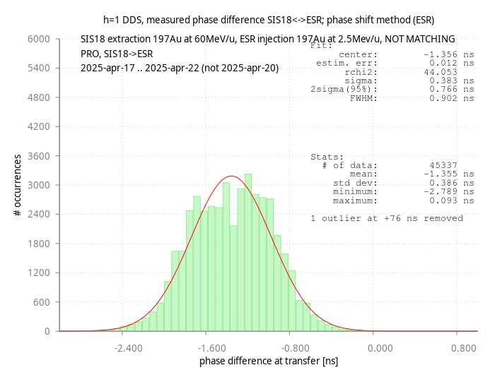 Figure: Histogram: Number of occurrences vs DDS phase difference of both rings at transfer. Details see text.
The figure shows a histogram where the number of occurrences is plotted vs the DDS phase difference between both ring machines at transfer. The histogram roughly resembles a Gaussian. The standard deviation (386 ps) and the sigma of the fit (383 ps) agree rather well and the the FWHM is about 900 ps. With one outlier at +76 ns excluded, the window defined by minimum and maximum value is close +/- 1.5 ns. The centre of the distibution is shifted into the negative direction by about 1.4 ns. This shift should be investigated.
With respect to h=1 of SIS18 period of 2110 ns, the uncertainty in degree corresponds to
Figure: Histogram: Number of occurrences vs DDS phase difference of both rings at transfer. Details see text.
The figure shows a histogram where the number of occurrences is plotted vs the DDS phase difference between both ring machines at transfer. The histogram roughly resembles a Gaussian. The standard deviation (386 ps) and the sigma of the fit (383 ps) agree rather well and the the FWHM is about 900 ps. With one outlier at +76 ns excluded, the window defined by minimum and maximum value is close +/- 1.5 ns. The centre of the distibution is shifted into the negative direction by about 1.4 ns. This shift should be investigated.
With respect to h=1 of SIS18 period of 2110 ns, the uncertainty in degree corresponds to - FHWM (0.902 ps) -> 0.154 degree
- 1 sigma (383 ps) -> 0.065 degree
- 5 sigma (1915 ps) -> 0.326 degree
Summary
Although the frequency beating method - as expected - does not provide good results, it is still surprising that it works at all. The precision achieved via the phase shift method looks promising. The systematic shift of ~ -1.356 ns (-0.23 degree) still needs to be investigated. -- DietrichBeck - 2025-05-02

| I | Attachment | Action | Size | Date | Who | Comment |
|---|---|---|---|---|---|---|
| |
easter_sis18-esr_phasematch_fbeat.png | manage | 45 K | 2025-04-30 - 16:53 | DietrichBeck | frequency beating |
| |
easter_sis18-esr_phasematch_pshift-esr.png | manage | 64 K | 2025-04-30 - 16:52 | DietrichBeck | phase shift ESR injection |
This topic: TOS/BunchBucket > WebHome > BunchBucketDocumentation > BunchBucketDocuments > BunchBucketTestsMeasurements > BunchBucketTestMeasurement20
Topic revision: 2025-05-02, DietrichBeck
Topic revision: 2025-05-02, DietrichBeck
Ideas, requests, problems regarding GSI Wiki? Send feedback | Legal notice | Privacy Policy (german)