NTCAP User Guide
This document contains basic information about the NTCAP data acquisition system and instructions on how to use it. It is based on the doctoral dissertation of C. Trageser 1, the paper by Trageser et al 2, GSI report by R. Chen 3 as well as various documents collected in the NTCAP Seafile library.
Introduction
The New Time CAPture (NTCAP) system is a data acquisition (DAQ) setup used to record Schottky detector signals at the Experimental Storage Ring (ESR) at GSI. It is able to process signals in a frequency range between 10 MHz and 6.6 GHz. Additionally, relevant scaler signals can be recorded. These include data from particle detectors, in-ring beam diagnostics and control system timing signals.
NTCAP has been operated in different configuration: the “old” version (original NI chassis + original computer), a “temporary” solution (new NI chassis + plus borrowed computer) and a planned “new version” (new NI chassis + new computer).
April 2025 beamtime: We are using the old version of NTCAP!
Start-Up
To start the NTCAP system, make sure that the NI crate and the NAS are switched on before turning on the NTCAP computer. Connect to the NAS using the Synology Assistant. Now you can mount the NAS drives on the NTCAP computer: Open Windows Explorer, right click on “This PC” on the left and select “Map network drive…”. You should be able to select the folders “data1” and “data2” and map them to the drives “O:” and “P:” respectively. The standalone version of NTCAP can be started from the desktop.
Measurement Setup
 Image 1:
The NTCAP GUI (from 4)
Image 1:
The NTCAP GUI (from 4)
GUI The layout NTCAP GUI is separated into several fields: The “Control” panel is on the right over the ‘Settings’ panel. On the top left is the ‘Data Monitor’ which displays the acquired Schottky data, this can be switched off for better performance. Below are the ‘Measurement paths’ (ie the folders the IQ and SC files are currently being saved in), the ‘Buffer Monitor’ and an event log. Initialisation Once NTCAP has been started, the ‘Ready’ indicator in the “Control” panel should be on. At this point a path has to be specified where the data files will be stored. Under “Data-Files” and “SC-Files” in the settings panel paste the right path (usually to the “O:” and/or “P:” drive which are mapped to the NAS) in the field “Masterpath”. Check whether the correct carrier frequency is set. The other settings can usually be left as they are and should only be changed if you know what you’re doing. After clicking the ‘Init’ button on the left side of the ‘Control’ panel, the ‘Init’d’ indicator should turn to bright green. Settings marked as ‘Advanced’ (RF and IF attenuation) can now be changed and initialised using the ‘Adv. Init’ button. Again: Only do this if know what you’re doing! Start/Stop Check whether the settings and file paths are correct and that there are no error messages in the output field. Start the measurement by clicking the ‘Start’ button, the ‘Acquiring’ indicator should now turn bright green. Check that the folders for th IQ and SC files have been created in the desired location and that the first files are being filled. Use the data monitor to visualise the IQ data that is being recorded. When not in use, the data monitor should be turned off (the button is on the bottom right). If there is an interruption in data taking (ie loss of the beam) that is likely to last for more than a few minutes, stop the DAQ using the ‘Stop’ button. If you need to change any settings, stop the DAQ, change the settings, initialise and then re-start the measurement. Any interruption in data taking should be noted in the elog along with the reason and any changes that were made. Shutdown To shut down NTCAP, stop the measurement and click the red button on the top left of the window. You can now close the window. At the end of the beamtime, make sure that all data has been written to long-term storage along with all necessary documentation. Dismount the NAS shut down all all the software on the computer (NTCAP, NI MAX, Synology Assistant) and shut down the computer. Turn of the NI crate and the NAS.
Components
 Image 2: Overview
of the NTCAP setup (based on a graphic in 5)
Image 2: Overview
of the NTCAP setup (based on a graphic in 5)
NI Chassis
The modules comprising the DAQ are housed in a National Instruments (NI) PXIe-1095 crate based on the PXIe standard for experiment electronics. It provides 18 slots with PCIe buses of which two are reserved for a control and a timing module respectively. The crate replaces an older PXIe-1075 model which was used until 2024.
Vector Signal Analyzer
The vector signal analyzer (VSA) is a NI PXIe-5663E module which consists of three parts: a local oscillator (NI 5651), a downconverter (NI 5601) and a digitizer (NI 5622). The local oscillator provides a signal for the downconverter. It contains a voltage-controlled oscillator but in order to obtain higher precision the oven-controlled crystal oscillator (OCXO) of the timing module (see below) is used instead. The downconverter accepts the RF signal from the Schottky detector, downsamples it using the oscillator signal, filters it and passes it to the digitizer. The digitizer used an analog-to-digital (AD) converter to digitze the signal and a digital downconverter to extract the in-phase and quadrature (IQ) components. The IQ data is written to file and used for both online and offline analysis.
I/O Card
The setup contains two NI-6612 scaler cards with BNC-2121 connector accessories that provide six (eight?) inputs each for TTL signals. When connecting scaler signals make sure that they are TTL (not NIM)! Additionally, there is the possibility to assign data streams (eg clocks) from other modules in the NI chassis to scaler channels.
Timing Module
The NI 6674T timing module provides a signal from an oven-controlled crystal oscillator (OXCO) that is used by the VSA (see above). Additionally, the timing module accepts a read-out trigger, that is used to ensure a simultaneous start of the VSA and the scaler channels.
Interface Card
The PXIe-PCIe8375 interface cards connects the crate with the NTCAP computer via a fibre optics cable. The maximum data rate is 838 Mbytes/s which is about five times the maximum data rate produced by the experiment. Using fibre optics cables also provides galvanic isolation of the computer form the crate.
Network Attached Storage
The network attached storage (NAS) consists of a Synology DS3612xs diskstation with 12 internal hard disks that provide 10 TB of storage each.
Additionally, there are two Synology DX1211 expansion units available, which are, however, not connected at the moment. The NAS is connected to the NTCAP computer via a 10 GBit network switch.
NTCAP computer
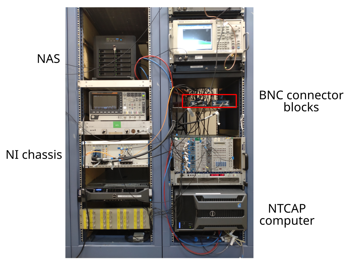 Image 3:
Placement of NTCAP components in the rack in the ESR electronics
hut.
Image 3:
Placement of NTCAP components in the rack in the ESR electronics
hut.
Data Formats
The IQ data from the Schottky detector and the data from the scaler channels (SC) are stored in separate files. For both file types the TDMS format developed by National Instruments is used 6. The filenames consist of a running number, the token ‘IQ’ or ‘SC’ to differentiate the data type, and the suffix tdms. The three components are separated by full stops, eg ‘0000000.iq.tdms’. The IQ and SC files are stored in separate folders that are created at the beginning of the measurement. The names of the folders start with the token ‘IQ’ or ‘SC’ followed by a timestamp (format: YYYY-MM-DD_hh-mm-ss, ie year-month-day_hour-minutes-seconds).
The data files consist of a file header, a frame header and the data itself. The file header contains important paramters of the NTCAP system relating to the VSA and the scaler I/O card respectively. The frame header of the IQ files contains a timestamp, the time step between to sample points, the gain and the offset of the measurement. The frame header of the SC files contains only a timestamp. The data in the IQ files is split into two data channels recording the in-phase and quadrature components of the measurement in 16-bit integer values. Using the gain and offset values in the frame header this can be converted to the in-phase and quadrature values in Volt. The data in the SC files is split into 16 channels - one for each scaler channel - and store UINT32 type values.
File Storage
Troubleshooting
- Have you tried turning it off and on again?
- Check the event log in the gui.
- On the old NTCAP computer: Document error messages etc. by taking screenshots with the ‘Snipping Tool’ (avalaible from the toolbar).
- Use the NI Measurement & Automation Explorer (NI MAX) application to check the status (eg temperature) and connection of the NI modules. After expanding the NI chassis tab you can click on the individual modules and run a self-test. If the downconverter (PXISlot12) is “not configured” this needs to be done by clicking on ‘Configure’ and then specifying the digitizer (PXISlot13) and the local oscillator (LO, PXISlot11).
ToDo
- Startup: which version of NTCAP to use?
- picture of NI chassis
- document scaler channel assignment
- which scaler channels can actually be used (the dissertation disagrees with the earlier User Manual)
- old vs new setup
- more detail on possible measurement settings in the gui
C. Trageser, Dissertation, Justus-Liebig-Universität Gießen, 2018 (in German)↩︎
R. Chen, Online data analysis system for isochronous schottky mass spectrometry experiment, GET INvolved Report, GSI, 2018↩︎
C. Trageser, Dissertation, Justus-Liebig-Universität Gießen, 2018 (in German)↩︎
C. Trageser, Dissertation, Justus-Liebig-Universität Gießen, 2018 (in German)↩︎
Ideas, requests, problems regarding GSI Wiki? Send feedback | Legal notice | Privacy Policy (german)