Using the GSI-HVSwitch2 Class
Class for a six channel fast switching power supply. Such a switch can be used to switch between two programmable voltages depending on an external hardware trigger signal. This device was developped by Harald Hahn, EE/KS/GSI. Each object of the GSI-HVSwitch class just controls one channel of that power supply.Specifications (Spring 2010)
The main idea is to switch electrodes fast (microsecond full range). The device was mainly built for trap experiments that need to switch electrodes when capturing or ejecting ions.- Input
- Trigger Signal, 4V, 3mA, Lemo, state indicated via LED
- Interlock, no interlock (<50 Ohm), interlock (>50 Ohm), Lemo, indicated via LED
- Output
- Level 0V..+/-200VDC
- Current 20mA
- Rise/Falltime 300V/us (load 10k/100pF)
- Ripple 300mVss (can be reduced using external power supplies).
- BNC connector
Configuration of COM-Ports and Cable.
Typically, the power supply is tested by using a serial RS485 interface from National Instruments. However, also other serial interfaces might work (see below).Configuration of COM-Port
Most parameters of the RS-485 interface, like the Baud-Rate, are set programmatically. However, it is important that the wiring is properly configured. When using a serial card from NI, you have to use the MAX and configure the port to "2 Wire Auto"Wiring
The cable is connected via a three-pin plug to the back of the crate. The assignment of the pins and their meaning can be seen from the figure below. For the pin layout of your RS-485 interface card, check the documentation of the manufacturer (for NI cards, have a look at the "Serial Quick Reference Guide").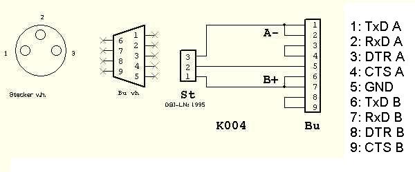
Using the Device
Bus Addresses
Please note, that the module addresse must be given in HEX format. The module addresses in the first crate are 08, 10, 20, 40, 28 and 00. The offset to the module addresses can be changed on the backplane of a crate (for "old" crates, the coding plug needs to be changed). Typically, the modules use a Baud rate of 115200 Baud.Trigger Signals
The trigger signal (via standard Lemo) requires TTL levels to switch between the two states. Attention: High-Voltage safety requires a hardware design using an opto-coupler at the trigger input. As a result, the trigger input needs slightly more current than the TTL specification. If you use standard TTL signals, you will have trigger problems. Hence, you may need to use additional line-drivers.Usage in "Stepping Mode"
As an alternative, more than two voltages can be programmed. After these voltages have been transferred to the device, they are stored in a kind of ring-buffer. When receiving trigger signals, the device switches to the next voltages step with each edge of the trigger signal. This operational mode is a bit special. Please consider the following.- Avoid triggering the device when programming the voltages via the serial interface.
- The time between two edges of the trigger signal should be longer than 100 microseconds.
- The maxim number of voltage step is around 40 (maybe 200 in the future).
Firmware Revisions
The devices differ in functionality depending on the configuration of the hardware and the firmware All firmware revisions support switching between two voltages and reading the actual voltage and temperatures. In addition the revision- "htrp0 ..." supports
- enabling/disabling the output of a module by software.
- "Stepping Mode"
Structure of the Software
- The class GSI-HVSwitch2 uses the the instrument driver HVSwitch2Driver.
- The instrument driver HVSwitch2Driver uses the instrument driver SDEXDriver.
- The SDEXDriver finally uses VISA (and finally the RS485 driver).
Using Other Serial Hardware
As an alternative to serial hardware from National Instruments, other hardware may also be used - of course. But then it is up to you to figure out its configuration. As an example, Harald Hahn has tested an interface card from WuT. The DIP switches must be configured as follows:- 1 on
- 2 on
- 3 off
- 4 on
- 5 off
- 6 on
- 7 on
- 8 off
This topic: CSframework > WebHome > Documentation > CsDocMain > CsGSI-HVSwitch2
Topic revision: 2010-09-07, DietrichBeck
Topic revision: 2010-09-07, DietrichBeck
Ideas, requests, problems regarding GSI Wiki? Send feedback | Legal notice | Privacy Policy (german)